Page 2 - Warranty and Service
2 Warranty and Service Powermatic ® warrants every product it sells against manufacturers’ defects. If one of our tools needs service or repair, please contact Technical Service by calling 1-800-274-6846, 8AM to 5PM CST, Monday through Friday. Warranty Period The general warranty lasts for the time ...
Page 3 - Table of Contents
3 Table of Contents Warranty and Service .................................................................................................................................... 2 Table of Contents ...........................................................................................................
Page 4 - not
4 Warnings 1. Read and understand the entire owner's manual before attempting assembly or operation. 2. Read and understand the warnings posted on the machine and in this manual. Failure to comply with all of these warnings may cause serious injury. 3. Replace the warning labels if they become obscu...
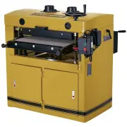
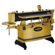
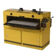
Page 6 - Features
Page 7 - Specifications
7 Specifications Model Number .................................................... DDS-225 ....................... DDS-237 ....................... DDS-237 Stock Number ..................................................... 1791290 ........................ 1791320 ........................ 1791321 Main...
Page 8 - Unpacking; Shipping Contents; NOT
8 Unpacking Open the shipping crate and check for shipping damage. Report any damage immediately. Read the owner’s manual thoroughly for assembly, maintenance and safety instructions. Shipping Contents Note 1: Some parts are inside a box in the cabinet. Note 2: Models DDS-225 and DDS-237 Drum Sander...
Page 9 - Assembly; Handwheel Assembly; Electrical Connections; Electrical connections must be
9 Exposed metal surfaces, such as the shafts on the drums and pressure rollers, have been given a protective coating at the factory. This should be removed with a soft cloth moistened with kerosene. Do not use acetone, gasoline, or lacquer thinner for this purpose. Do not use solvents on plastic par...
Page 10 - Abrasive Paper Installation; Disconnect machine from
10 permanent wiring system; or to a system having an equipment-grounding conductor. Make sure the voltage of your power supply matches the specifications on the motor plate of the machine Abrasive Paper Installation Disconnect machine from power source. Proper attachment of the abrasive strips to th...
Page 11 - Adjustments; Drum Height
11 drum. Continue to wrap the abrasive in a clockwise spiral fashion by rotating the drum with your left hand and guiding the strip with your right hand (Fig. 11). Successive windings of the strip should be flush with previous windings without any overlap. 7. The left end of the drum which contains ...
Page 12 - Pressure Rollers; Do not over tighten the; Table Height
12 Pressure Rollers The pressure rollers (Fig. 15) maintain tension upon the workpiece as it passes through the machine. The spring tension of the pressure rollers has been factory set. If a board refuses to pass through the machine, or the finished surface of a board is uneven, the spring tension o...
Page 13 - Lead Screw Thread Clearance
13 4. Insert a tool, such as a hex wrench or screwdriver, through the hole on top of the leadscrew (Fig 18) at that corner of the table that is lowest. 5. Turn the leadscrew clockwise to raise the table. 6. When the adjustment is complete, install the chain over the four sprockets, and over the chai...
Page 14 - Conveyor Belt; Do not over tighten the convey-; Drive Belts
14 Conveyor Belt Conveyor belt tension and tracking adjustments may occasionally be necessary during break-in and normal operation to compensate for belt stretching. Adjust the tension of the conveyor belt by turning the knobs (Fig. 20) clockwise to increase tension, counterclockwise to decrease ten...
Page 15 - Pulley Alignment; Changing Belts; The drums are heavy – use
15 Pulley Alignment The drum and motor pulleys must be in line so that the belts are straight. To check this: Place a straight edge, such as a metal ruler, against the flat sides of the motor pulley and a drum pulley (Fig. 23). If the straight edge does not lie flush on the flat sides of the pulleys...
Page 16 - Maintenance; Operations; Basic Operation
16 Maintenance Note: See also Maintenance Checklist on page 19. For best results, perform the following proced-ures on a routine basis: Grease the four leadscrews on the table. Lubricate the bushings at each end of the pressure rollers. Use a dry type lubricant for this, such as graphite or sili...
Page 17 - Allow the conveyor belt to; Abrasives; Grits that are too fine can
17 Edge Sanding When edge sanding, the sander will mimic the opposite edge of the stock which is lying on the conveyor belt. Because of this, it is important for the stock edge to have been ripped at the proper angle to the face before the sanding process. When edge sanding small stock, clamp severa...
Page 18 - Extending Abrasive Life; Switch Lock
18 Cloth backed abrasives may also be cleaned by soaking in paint thinner or mineral spirits for 20 minutes to 1 hour, then using a brush to remove any build-up or burns. Dry the abrasive strips completely before reuse. Extending Abrasive Life . Abrasive life can also be increased by removing the ab...
Page 19 - Troubleshooting; Performance Problems; Problem
19 Maintenance Checklist Note: See also the Maintenance section on page 16. Work area around machine marked off clearly. Non-skid floor strips in area where operator normally stands. Inspect entire machine for loose bolts, nuts, screws. Tighten and replace as necessary. Clean conveyor and dr...
Page 20 - Mechanical & Electrical Problems; Possible Cause
20 Mechanical & Electrical Problems Problem: Machine will not start, restart, or repeatedly trips circuit breaker or blows fuses Possible Cause Solution 1. No incoming power 2. Overload automatic reset has not reset 3. Sander trips frequently 4. Building circuit breaker trips or fuse blows. 5. L...
Page 21 - Parts – DDS-225 Sander; Drum Assembly – DDS-225; Description
21 Parts – DDS-225 Sander Drum Assembly – DDS-225 Index No. Part No. Description Size Qty 1 ............... DDS225-101A .......... Rear Drum ( serial no. 1009DDS2252795 and higher) .................................... 1 2 ............... DDS225-102A .......... Abrasive Fastener-Right ( serial no. 10...
Page 23 - Conveyor Assembly – DDS-225
23 Conveyor Assembly – DDS-225 Index No. Part No. Description Size Qty 1 ............... DDS225-201 ............ Table .................................................................... .................................... 1 2 ............... DDS225-202 ............ Support Bracket, Left-Front ......
Page 28 - Gearbox Assembly – DDS-225
28 Gearbox Assembly – DDS-225 Index No. Part No. Description Size Qty 1 ............... DDS225-401A ......... Gearbox Body ( serial no. 0506DDS225584 and higher) ................................ 1 2 ............... TS-0720071 ............. Lock Washer ...................................................
Page 30 - Parts – DDS-237 Sander; Drum Assembly – DDS-237
30 Parts – DDS-237 Sander Drum Assembly – DDS-237 Index No. Part No. Description Size Qty 1 ............... DDS237-101B .......... Rear Drum ( serial no. 1008DDS2370150 and higher ) ................................... 1 2 ............... DDS225-102A .......... Abrasive Fastener-Right ( serial no. 10...
Page 32 - Conveyor Assembly – DDS-237
32 Conveyor Assembly – DDS-237 Index No. Part No. Description Size Qty 1 ............... DDS237-201 ............ Table .................................................................... .................................... 1 2 ............... DDS225-202 ............ Support Bracket, Left-Front ......
Page 34 - Motor and Cabinet Assembly – DDS-237
34 Motor and Cabinet Assembly – DDS-237 Index No. Part No. Description Size Qty 1 ............... DDS237-301 ............ Cabinet ................................................................. .................................... 1 2 ............... DDS237-302 ............ Support Bracket-Front ....
Page 37 - Gearbox Assembly – DDS-237
37 Gearbox Assembly – DDS-237 Index No. Part No. Description Size Qty 1 ............... DDS225-401A .......... Gearbox Body ...................................................... .................................... 1 2 ............... TS-0720071 ............. Lock Washer ..............................
Page 40 - Wiring Diagrams
40 Wiring Diagrams DDS-225 Sander 5 L3 A1 3 L2 13 NO 1 L2 17 18 2 T1 4 T2 6 T3 14 NO 2 T1 4 T2 6 T3 A2 G ROUND G REEN RE D B LACK B LACK W HITE G REEN B LACK RED 98 96 95 97 250VAC150MFD 450VAC 30UF G REEN B LACK RED G REEN B LACK RED RED B LACK G REEN W HITE YEL LOW S 6 R FRONT U BACK B LACK RED V ...