Page 2 - Table of Contents; Installation Manual
Table of Contents Installation Manual Operating Instructions......... 9 1. Remote Buttons Overview.............................. 9 2. Remote Controller LED Screen And Icons.... 10 3. Handling the Remote Controller................... 11 4. Controlling the System’s Airflow.................... 12 5. In...
Page 4 - Page 4; serious; Safety Precautions; or a; CAUTION; WARNING; can cause undesirable operation, fire, or electrical shock.
Page 4 This symbol indicates that ignoring the related instructions may cause death, or serious injury. This symbol indicates that ignoring the related instructions may cause moderate injury to nearby persons, and/or damage to your appliance or other property. Safety Precautions Read and Underst...
Page 5 - Page 5; Note about Fluorinated Gasses
Page 5 6. For all electrical work, follow all local and national wiring standards, regulations, and especially this Installation Manual. You must use an independent circuit and a dedicated breaker to supply power. Do not connect other appliances to the same circuit. Insufficient electrical capac...
Page 6 - System Components; High Wall-Mounted Air Conditioner; the wall of the dwelling using suitable mounting brackets.; Page 6
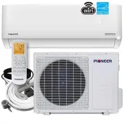
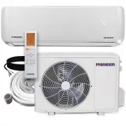
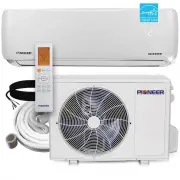
1 System Components High Wall-Mounted Air Conditioner The system is made up of two or more units connected together via insulated copper pipes and an electrical communication cable. The indoor unit is mounted onto one of the walls in the room that is to be conditioned. The outdoor unit is installed ...
Page 7 - Included Accessories; Page 7; x; Warranty Card; x; Set of Mounting Plate Screws; x; Plastic Drain Joint Plug; Connecting Pipe Diameters; Accessories and Components:
2 Included Accessories 1x Installation and Owner’s Manual 1x 16 ft. Communication Cable SPLIT-TYPE ROOM AIR CONDITIONER CS78421-548-754 IMPORTANT NOTE: Read this manual carefully before installing or operating your new air conditioning unit. Make sure to save this manual for future reference. Instal...
Page 8 - Page 8; Indoor Unit Overview; Front Panel Display; Emergency; Emergency Manual Button
Page 8 Indoor Unit Overview 3 Owner’s Manual 3 1 2 5 4 4 2 3 No. Description Symbol LED Icon 12345 Indicates that the unit is currently powered on POWER SLEEP TIMER RUN Temp. Display Indicates that the system is currently in SLEEP mode Displays the current set temperature or any error codes Indi...
Page 9 - Page 9; Operating Instructions; Remote Buttons Overview
Page 9 Owner’s Manual Operating Instructions The display and some features of the remote control may vary according to the model of the system. The shape and positions of the buttons and indicators may vary according to the model of the system, but the features and functionality would remain the...
Page 10 - NOTE ON ILLUSTRATIONS; Remote Controller LED Screen and Icons
Page 10 4 NOTE ON ILLUSTRATIONS The illustrations in this manual are strictly for explanatory purposes. The actual display and some functions of the remote controller may vary according to the model purchased. Operating Instructions No. Description Icon 10 3456 Auto Mode Cooling Mode Signal Tran...
Page 11 - Replacement of Batteries; Signal; Operating the Remote Controller Sucessfully and Safely; Switch Position; COOL; Functional Result; Temp. Units are Celsius; Heating + Cooling Operation
Depending on the system, the control type (Cooling Only or Heat Pump) and the unit of Temperature (°C or °F) can be configured using the manual dip-switches below the battery compartment. Operate as below: Page 11 4 Operating Instructions Owner’s Manual Replacement of Batteries Remove the batter...
Page 12 - Regarding the Airflow of the Indoor Unit; • Do not manipulate the louvers themselves
4 Operating Instructions Page 12 CAUTION Regarding the Airflow of the Indoor Unit The air that is pulled in by the fan (the “return air”) enters the grille and is passed through the filter. It is then cooled/dehumidified/heated through the heat exchanger. The direction of the air output is manip...
Page 13 - COOLING Mode; HEATING Mode; NOTE
Page 13 COOLING Mode Cooling mode allows the air conditioner to cool the room while also reducing the humidity of the air in the room. To put the system into cooling mode, press the button until the symbol appears on the remote’s display. The and buttons can then be used to set a temperature low...
Page 14 - DRY Mode; AUTO Mode
Page 14 DRY Mode Dry mode is a limited function that can rapidly reduce the humidity/moisture of the room. To put the system into dry mode, press the button until the symbol appears on the remote’s display. An automatic preset of this mode is then activated. 4 Operating Instructions Owner’s Manu...
Page 15 - Turning the Display On or Off; SLEEP Mode
Page 15 Turning the Display On or Off The LED display on the front panel of the system can be turned on or off as desired. To do so, press the button in order to switch off the LED display on the front panel. This button can be pressed again to turn the LED display back on. 4 Operating Instructi...
Page 16 - The ECO feature is available in both COOLING; TURBO Option
Page 16 Energy Saver (ECO) Option In this mode, the appliance will automatically manage the operation in order to save energy. To turn the ECO feature on, press the button on the remote, and the icon will appear. The system is now running in ECO, and the process can be repeated to turn it off. 4...
Page 17 - NOTE Regarding Timers; Using the Timer - TIMER ON; then; Using the Timer - TIMER OFF
Page 17 NOTE Regarding Timers • Press the button to cancel at any time in Timer Off. • The programming will cancel if no buttons are pressed after 5 seconds. This may require restarting the process. Using the Timer - TIMER ON The TIMER feature allows you to set a time delay for the system to tur...
Page 18 - 6°F Freeze Protection Function
Page 18 4 Operating Instructions Owner’s Manual 46°F Freeze Protection Function This feature is meant to be used to prevent freezing while the user is away from home. When turned on, it sets the system to keep a temperature of 46°F. If the unit is in standby, then the setting will automatically ...
Page 19 - I FEEL - To Ensure Comfort; Note: The I FEEL feature will automatically de-activate
Page 19 I FEEL - To Ensure Comfort The I FEEL feature enables the remote to act as the temperature sensor and relay the current air temperature of where the remote is physically placed within the room. In some cases, this can aid with reducing thermal drift between the set temperature and the ac...
Page 20 - An Important Note Regarding Operating Temperatures; temperatures goes outside of these ranges.; Inverter Air Conditioner
Page 20 NOTE After stopping and restarting the air conditioner, or after the mode is changed during operation, the system does not restart immediately, and will come on when three minutes have elapsed (as a protection for the compressor). 4 Operating Instructions Owner’s Manual An Important Note...
Page 21 - Periodic Maintenance Is Essential For The System!; Indoor Unit; er; The filter; Interior of the Indoor Air Handler; Maintenance of the Air Conditioner; BEFORE CLEANING OR MAINTENANCE
In addition to the filters, the interior of the indoor unit itself as well as the inner coil should be inspected every season. The front panel can be disconnected and removed from the top hinge where the pegs connect. This will allow for easier inspection of the interior and behind the air filters. ...
Page 22 - Indoor Unit Installation Location Selection; install the unit on a wall that is subject to vibrations.; Indoor Unit Installation Instructions; or more
Indoor Unit Installation Location Selection Follow the below best practices for selecting an optimal space for installation the indoor unit: • DO NOT install the unit on a wall that is subject to vibrations. • DO NOT install the system near sources of heat, steam, or flammable gases. • DO NOT instal...
Page 23 - Installation Diagram
Installation Diagram Before proceeding, it is important to consider the following height and length restrictions: Before starting the installation, decide on the position of both the indoor and outdoor units. Take into account the minimum clearance requirements for both the indoor and outdoor units,...
Page 24 - Indoors
Installation of the Mounting Plate 1. Place the included mounting plate against the wall where the system will hang that fulfills the constraints on page 22. Use a level to ensure that the plate is horizontally level. 2. Drill 1.3” deep holes for each screw to enter, the locations are flexible but s...
Page 25 - Electrical Connections - Indoor Unit; BEFORE PERFORMING ELECTRICAL WORK, READ THESE REGULATIONS; licensed electrician.; BEFORE PERFORMING ANY ELECTRICAL OR WIRING WORK,
Electrical Connections - Indoor Unit All systems will include a wiring diagram affixed to the indoor unit. See Page 44 for more details. 1. Lift up the front panel of the indoor unit. 2. Remove the cover as indicated in the illustration. 3. For the electrical wiring, consult the circuit diagram affi...
Page 26 - Preparing the Refrigerant Piping of the Indoor Unit; that water can flow freely.; Ensure that the bundle is exiting at a continuous downward pitch.; Be extremely careful not to kink any piping.
Preparing the Refrigerant Piping of the Indoor Unit The piping “pigtails” pre-attached to the indoor unit can be run in 3 different ways as shown in the illustration. Decide which type of configuration is most suitable before continuing. By default it is routed for a left side exit as shown in #1. T...
Page 27 - Connecting the Drain Hose; NOTE ON DRAIN HOSE PLACEMENT; DO NOT; DUAL DRAIN HOLE LOCATIONS EXIST; YES
Connecting the Drain Hose By default, the drain hose is attached to the left-hand side of unit (”left” when facing the back of the unit). However, it can also be attached to the right-hand side. 1. To ensure proper drainage, attach the drain hose on the same side that your refrigerant piping exits t...
Page 28 - Consult the; It is vital; Power Supply Cable
Connecting the Signal Cable Cable Wire Specifications (For Uncommon Configurations) Color selection does not matter as much as matching number to number does. Consult the diagram affixed to the indoor and outdoor unit respectively for specific wiring instructions. There are 3 terminals (1, 2 , 3) an...
Page 29 - Torque Wrench; Covered by Vinyl Tape
Connecting the Refrigerant Piping to the Indoor Unit Wrapping the Lines and Mounting the Indoor Unit Once the copper piping kit coil is unwound, refer to the below instructions to proceed: 1. Bring the ends of both the copper line and the indoor unit line together. Align the centers of the pipes tha...
Page 30 - Outdoor Unit Installation Location Selection; install the unit near sources of heat, steam, or flammable gases.; Outdoor Unit Installation Instructions; Minimum Required Installation Space; SPECIAL CONSIDERATIONS FOR EXTREME
Outdoor Unit Installation Location Selection Follow the below best practices for selecting an optimal space for installation the indoor unit: • DO NOT install the unit near sources of heat, steam, or flammable gases. • DO NOT install the system in areas prone to extreme winds or dust. • DO NOT insta...
Page 32 - BEFORE PERFORMING; USE THE RIGHT CABLE; BEFORE PERFORMING ANY ELECTRICAL; North America; INDOOR UNIT TERMINAL POSITION #1 connects
Page 32 7 Outdoor Unit Installation Instructions Outdoor Unit Installation BEFORE PERFORMING ANY ELECTRICAL WORK, READ THESE REGULATIONS 1. All wiring must comply with local and national electrical codes, and must be installed by a fully-licensed electrician. 2. All electrical connections must b...
Page 33 - Power/Signal Electrical Wiring to the Outdoor Unit; The outside unit’s terminal block is protected; Cover
Power/Signal Electrical Wiring to the Outdoor Unit On the outdoor unit, the wiring diagram is located in the inner side of the handle cover. The outside unit’s terminal block is protected by an electrical wiring cover on the side of the unit. A comprehensive wiring diagram is printed on the inside o...
Page 34 - Connection of the Refrigerant Piping; K; Connection Instructions –; DO NOT DEFORM PIPE; Hold the pipe at a downward angle to
Connection of the Refrigerant Piping The length of refrigerant piping will affect the performance and energy efficiency of the unit. Nominal efficiency is tested on units with a pipe length of 5 meters (16 ft). Refer to the table below for specifications on the maximum length and drop height of pipi...
Page 35 - Step 3: Flare pipe ends; PIPING EXTENSION BEYOND FLARE FORM; Outer Diameter of; Step 4: Connect pipes; If provided by the supplier, apply leak; Connection Pipes
Page 35 7 Outdoor Unit Installation Instructions Outdoor Unit Installation Step 3: Flare pipe ends Proper flaring is essential to achieve an airtight seal. 1. After removing burrs from cut pipe, seal the ends with PVC tape to prevent foreign materials from entering the pipe. 2. Sheath the pipe w...
Page 36 - MINIMUM BEND RADIUS; Instructions for Connecting Piping; USE SPANNER TO GRAB THE; DO NOT USE EXCESSIVE TORQUE; Gas Tap; Liquid Tap
Page 36 7 Outdoor Unit Installation Instructions Outdoor Unit Installation MINIMUM BEND RADIUS When bending connective refrigerant piping, the minimum bending radius is 10 cm (4”). Radius ≥10cm (4 in) Instructions for Connecting Piping to Outdoor Unit 1. Unscrew the cover from the packed valve o...
Page 37 - Before using a vacuum pump and manifold gauge,; manifold gauge to service port on the; Ensure that the pin; ) Open the low pressure valve of the manifold; Vacuum Pump; BEFORE PERFORMING EVACUATION
Air Evacuation and Bleeding the Circuit The air and/or humidity left inside the refrigeration circuit can contaminate the refrigerant and cause abnormal spikes in pressure, leading to eventual compressor malfunction. Therefore, after having connected the indoor and outdoor units to create a closed s...
Page 38 - OPEN VALVE STEMS GENTLY
Evacuation Instructions (Cont’d) 6. Turn on the vacuum pump to evacuate the system. 7. Run the vacuum for at least 15 minutes, or until the Compound Meter reads -76cmHG (-100 kPa or -30 inHg). 8. Close the low pressure side of the manifold gauge, and turn off the vacuum pump. 9. Wait for 5 minutes, ...
Page 39 - Electrical/Gas Leak Check and Test Run; Note: This may not be required in some locations.; Soap and Water Method
Page 39 8 Electrical/Gas Leak Check and Test Run Electrical/Gas Leak Check ELECTRICAL SAFETY CHECKS After installation, confirm that all electrical wiring is installed in accordance with local and national regulations, and according to the Installation Manual. BEFORE TEST RUN Check Grounding Wor...
Page 40 - BEFORE TEST RUN; Only perform a test run after the following; TEST RUN INSTRUCTIONS; The following test run should be performed; AFTER TEST RUN COMPLETION
Test Run PASS/FAIL? Page 40 8 Electrical/Gas Leak Check and Test Run Test Run BEFORE TEST RUN Only perform a test run after the following steps have been completed: Electrical Safety Checks Gas Leak Checks No Electrical Leaks or Abnormal Noises Unit is Properly Grounded All Electrical Te...
Page 41 - MALFUNCTION
Page 41 9 Troubleshooting Troubleshooting MALFUNCTION If there are strange odors... If there’s running water... If the airflow is insufficient, and the air is not hot or cold enough... If the display is off... If a fine mist is coming from the air outlet... If the appliance does not respond to c...
Page 42 - Air Outlet; Anchoring the Outdoor Unit; Appendix; WHEN DRILLING INTO CONCRETE,; Air inlet
Pioneer WYT Series Mini Split MODEL/Capacity (Btu/h) A B D YN009ALFI22RPD (9,000 BTU - 110/120V) H YN012ALFI22RPD (12,000 BTU - 110/120V) YN009GLFI22RPD (9,000 BTU - 208/230V) YN012GLFI22RPD (12,000 BTU - 208/230V) YN024GLFI22RPD (24,000 BTU - 208/230V) Air Inlet Air Inlet Air Outlet 438 mm 17-1/4 i...
Page 43 - Guidelines for Drilling the Wall Hole
Guidelines for Drilling the Wall Hole Below are the suggested locations for the wall hole for systems between 9,000 - 24,000 BTU. Both left side/right side exits are considered. Confirm holes are appropriate by corner tracing. Page 43 A Appendix 5 7/8” 1 5/8” 12 1/16” 32 5/16” 1 3/4” 1 5/8” 6 11...
Page 44 - Guidelines for Drilling the Wall Hole (continued)
Left Side Exit Right Side Exit 1 5/8” 1 3/4” 2 1/8” 22 3/16” 11 7/8” 9 3/4” 1 5/8” 8 3/4” 13 ” 43 3/16” Ø 2 1/2” Ø 2 1/2” 1/2” (For 18K-24K Systems) All Distances in Inches Appendix Guidelines for Drilling the Wall Hole (continued) Simplified Wiring Diagram (115V and 230V) Page 44 A Appendix
Page 45 - European Disposal Guidelines; household waste or unsorted municipal waste.; • The manufacturer takes back the old appliance free of charge.; Special Notice; the food chain. Please follow proper disposal protocol.
European Disposal Guidelines This appliance contains refrigerant and other potentially hazardous materials. When disposing of this appliance, the law requires special collection and treatment. Do not dispose of this product as household waste or unsorted municipal waste. When disposing of this appli...
Page 46 - Tel; Scan the below code to visit our support page; support; s a
The design and specifications of this product are subject to change without prior notice as development continues. Consult with the sales agency or manufacturer for details. Refer to the equipment nameplate for all other applicable specifications. is a registered trademark of Parker Davis HVAC Inter...


 Pioneer CYB024GMFILCAD-16
User Manual
Pioneer CYB024GMFILCAD-16
User Manual
 Pioneer CYB036GMFILCBD-16
User Manual
Pioneer CYB036GMFILCBD-16
User Manual
 Pioneer CYB048GMFILCBD-16
User Manual
Pioneer CYB048GMFILCBD-16
User Manual
 Pioneer DYR1824GMFI18R
User Manual
Pioneer DYR1824GMFI18R
User Manual
 Pioneer DYR4260GMFI18R
User Manual
Pioneer DYR4260GMFI18R
User Manual
 Pioneer RYB009GMFILDAD-16
User Manual
Pioneer RYB009GMFILDAD-16
User Manual
 Pioneer RYB012GMFILDAD-16
User Manual
Pioneer RYB012GMFILDAD-16
User Manual
 Pioneer RYB018GMFILDAD-16
User Manual
Pioneer RYB018GMFILDAD-16
User Manual
 Pioneer RYB036GMFILDAD-16
User Manual
Pioneer RYB036GMFILDAD-16
User Manual
 Pioneer RYB048GMFILDAD-16
User Manual
Pioneer RYB048GMFILDAD-16
User Manual
 Pioneer UYB018GMFILCAD-16
User Manual
Pioneer UYB018GMFILCAD-16
User Manual
 Pioneer UYB024GMFILCAD-16
User Manual
Pioneer UYB024GMFILCAD-16
User Manual
 Pioneer UYB036GMFILCAD-16
User Manual
Pioneer UYB036GMFILCAD-16
User Manual
 Pioneer UYB048GMFILCAD-16
User Manual
Pioneer UYB048GMFILCAD-16
User Manual
 Pioneer WYS009AMFI20RL-16
User Manual
Pioneer WYS009AMFI20RL-16
User Manual
 Pioneer WYS009AMFI22RL-10
User Manual
Pioneer WYS009AMFI22RL-10
User Manual
 Pioneer WYS009AMFI22RL-16
User Manual
Pioneer WYS009AMFI22RL-16
User Manual
 Pioneer WYS009GMFI22RL-16
User Manual
Pioneer WYS009GMFI22RL-16
User Manual
 Pioneer WYS012AMFI20RL-16
User Manual
Pioneer WYS012AMFI20RL-16
User Manual
 Pioneer WYS012AMFI22RL-16
User Manual
Pioneer WYS012AMFI22RL-16
User Manual