Pioneer RYB048GMFILDAD-16 - Manuals
User Manual Pioneer RYB048GMFILDAD-16
Summary
CONTENTS 1. Precaution .................................................................................................................................................. 1 1.1 Safety Precaution ...........................................................................................................
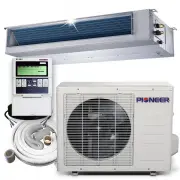
4 2. Part Names and Features 2.1 Model Names of Indoor/Outdoor units Series Capacity Indoor units Outdoor units Cassette 9K CB009GMFILCFHD YN009GMFI22RPD Duct RB009GMFILCFHD Console FB009GMFILCFHD Cassette 12K CB012GMFILCFHD YN012GMFI22RPD Duct RB012GMFILCFHD Console FB012GMFILCFHD Cassette 18K CB01...
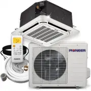
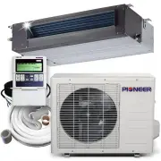
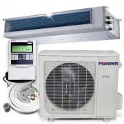
5 2.2 Part names of Indoor/Outdoor units Ceiling Cassette Unit
10 2.3.1.4 Easy maintenance Clean the filter (Optional, standard product without filter) It is easy to draw out the filter from the indoor unit for cleaning, even the filter is installed in rear side or bottom side. Replace the motor or centrifugal fan Remove the ventilated panel firstly. Remove...
11 The standard indoor unit can be controlled by wired controller. There is a display board with a receiver in the E-box. Move out the display, and fix it in other place, even in the distance of 10m. The unit will realized remoter control. The wired controller and the display board can display...
12 2.3.2 Cassette Unit 2.3.2.1 Lower Noise Optimize air channel system design to ensure the maximum quietness and comfort. Noise max down 6dB. 2.3.2.2 Turbo mode (Optional) Turbo function can boost cooling or heating speed in a short period, and makes the room cool down or heat up rapidly. 2.3...
13 2.3.2.6 Build-in Drain Pump The drain pump can lift the condensing water up to 750mm upmost. It’s convenient to install drainage piping under most space condition. 2.3.2.7 Terminals for alarm lamp and long-distance on-off controller connection are standard Reserve terminals for the connecti...
14 2.3.3 Console 2.3.3.1. Modern and elegant appearance The simple and stylish designs can nicely harmonies with your living space. 3.2.3.2. Four panels optional 2.3.3.3. Two air-outlet ways Cooling mode Quick Cooling To maintain room temp Air outlet from top and bottom to make quick cooling ---...
15 Heating mode Anti-cold air ------When the AC is just turn on, temperature of evaporator is very low, in this case, in order to prevent cold air direct blowing, only the upper louver is opened in a high position, the lower louver closed. 2.3.3.4. Four air inlets 2.3.3.5. Low noise DC indoor fa...
17 2.3.1.4 Optional drainage pipe connection Both right side and left side drainage holes are available to avoid the space limitation for drainage pipe installation. Make you more convenient during installation. C Panel (LED display) D Panel 2.3.1.5 Convenience operating and easy maintenance Rem...
18 3. Dimension 3.1 Indoor Unit Duct Units A C B D J I K Air filter ( optional ) air inlet from rear side air inlet from bottom side F E G H Electric control box Air filter ( optional ) L 4-install hanger Gas side Liquid side M W1 W2 H1 H2 25 Drain connecting pipe ( for pump ) Test mouth & Test ...
20 Cassette Units (24K, 36K, 48K) 840 84 0 950 950 C Test mouth & Test cover Drain hole 32 Wiring connection port 680 78 0 78 0 680 136126 91 196 132 A A B A A B A A B A B Service hole fordraining pump Fresh air intake 75 55 80 80 4-install hanger Gas side Liquid side E-parts box 135 90 Panel Bo...
21 Console Units 16 Drain pipe 195 Hanging arm Unit: mm 700 60 0 210
23 3.2 Outdoor Unit Note: The above drawing is only for reference. The appearance of your units may be different. Model W D H W1 A B YN009GMFI22RPD mm 770 300 555 840 487 298 inch 30.3 11.8 21.9 33.1 19.2 11.7 YN012GMFI22RPD mm 800 333 554 870 514 340 inch 31.5 13.1 21.8 34.3 20.2 13.4 YN018GMFI22RP...
24 4. Service Space 4.1 Indoor Unit Duct Units Ensure enough space required for installation and maintenance. 200mm(7.87in) or more 300mm(11.81in) or more 600mmx600mm/23.62inx23.62in Check orifice All the indoor units reserve the hole to connect the fresh air pipe. The hole size as following Cassett...
27 5. Refrigerant Cycle Diagram LIQUID SIDE GAS SIDE HEATEXCHANGE(EVAPORATOR) HEATEXCHANGE(CONDENSER) Compressor 2-WAY VALVE 3-WAY VALVE 4-WAY VALVE COOLING HEATING T2B Evaporatortemp. sensoroutlet T1 Room temp.sensor T3 Condensertemp. sensor T5 Dischargetemp. sensor T4 Ambienttemp. sensor INDOOR OU...
39 Outdoor Controller Set of For YN009GMFI22RPD, YN012GMFI22RPD: For YN018GMFI22RPD:
42 RB012GMFILCFHD Code 0 Code 1 Code 2 Code 3 Code 4
47 8 Electric Characteristics Model Indoor Unit Hz Voltage Min. Max. CB009GMFILCFHD 60 208-230V 187V 253V RB009GMFILCFHD 60 208-230V 187V 253V FB009GMFILCFHD 60 208-230V 187V 253V CB012GMFILCFHD 60 208-230V 187V 253V RB012GMFILCFHD 60 208-230V 187V 253V FB012GMFILCFHD 60 208-230V 187V 253V CB018GMFI...
48 9 Sound Level 9.1 Indoor unit Suction Discharge Microphone 1.4m Concealed Duct Type Duct Duct Model Noise level dB(A) H M L RB009GMFILCFHD 37 34 31 RB012GMFILCFHD 39 36 32 RB018GMFILCFHD 35 33 31 RB024GMFILCFHD 50 47 45 RB036GMFILCFHD 53 49 45 RB048GMFILCFHD 44 47 41
51 9.2 Outdoor unit Note: H= 0.5 × height of outdoor unit Model Noise Level dB(A) YN009GMFI22RPD 56 YN012GMFI22RPD 57 YN018GMFI22RPD 59 YN024GMFI22RPD 61 YN036GMFI17RUD 65 YN048GMFI17RUD 63 H 1.0m Outdoor Unit Microphone
52 10 Accessories Duct Units Name Shape Quantity Tubing & Fittings Soundproof / insulation sheath 2 Binding tape 1 Seal sponge 1 Drainpipe Fittings (for cooling & heating) Drain joint 1 Seal ring 1 Wired controller & Its Frame Wired controller 1 Others Owner , s manual 1 Installation man...
54 11 The Specification of Power Type 9K-18K 24K Power Phase 1-phase 1-phase Frequency and Voltage 208-230V, 60Hz 208-230V, 60Hz Circuit Breaker/ Fuse (A) 25/20 40/30 Indoor Unit Power Wiring (mm 2 ) Indoor/Outdoor Connecting Wiring Ground Wiring 2.5 2.0 Outdoor Unit Power Wiring 3×2.5 3×2.0 High Vo...
56 12 Installation Details 12.1 Location selection 12.1.1 Indoor unit location selection The place shall easily support the indoor unit’s weight. The place can ensure the indoor unit installation and inspection. The place can ensure the indoor unit horizontally installed. The place shall all...
58 12.2.2 Cassette indoor unit installation 12.2.2.1 Service space for indoor unit 12.2.2.2 Bolt pitch 12.2.2.3 Install the pendant bolt Select the position of installation hooks according to the hook holes positions showed in upper picture. Drill four holes of Ø12mm, 45~50mm deep at the selected po...
59 The body's lower part should sink into the ceiling for 10~12 mm. In general, L is half of the screw length of the installation hook. Locate the air conditioner firmly by wrenching the nuts after having adjusted the body's position well. 12.2.2.5 Install the panel Remove the grille Hang the panel ...
60 12.2.3.2 Install the main body Fix the hook with tapping screw onto the wall Hang the indoor unit on the hook. (The bottom of body can touch with floor or suspended, but the body must install vertically.) 14.2.1 Ceiling-floor unit installation 14.2.1.1 Service space for indoor unit 12.2.1.2 B...
61 14.2.1.3 Install the main body ① Ceiling installation (The only installation method for the unit with drain pump) Remove the side board and the grille. Locate the hanging arm on the hanging screw bolt. Prepare the mounting bolts on the unit. Put the side panels and grilles back. ② Wall-mounted in...
62 Model B C D mm inch mm inch mm inch 9K 549 21.61 325 12.80 350 13.78 12K 549 21.61 325 12.80 350 13.78 18K 560 22.05 335 13.19 360 14.17 24K 640 25.20 405 15.94 448 17.64 36K 640 25.20 405 15.94 448 17.64 48K 634 24.96 404 15.91 448 17.64 14.3.3 Install the Unit Since the gravity center of the un...
63 1/2" (12.7) 15.4 15.8 5/8" (15.9) 18.6 19.1 3/4" (19) 22.9 23.3 After flared the pipe, the opening part must be seal by end cover or adhesive tape to avoid duct or exogenous impurity come into the pipe. 7. Drill holes if the pipes need to pass the wall. 8. According to the field con...
64 vacuum pump. Confirm that the gauge needle does not move (approximately 5 minutes after turning off the vacuum pump). 7) Turn the flare nut of the 3-way valves about 45° counterclockwise for 6 or 7seconds after the gas coming out, then tighten the flare nut again. Make sure the pressure display i...
66 7). Mount the valve stems nuts and the service port cap Be sure to use a torque wrench to tighten the service port cap to a torque 18N.m. Be sure to check the gas leakage. 12.4.6 Re-installation while the outdoor unit need to be repaired 1. Evacuation for the whole system Procedure: 1). Confirm t...
68 Drainage pipe Water flow Drainage pipe Drainage pipe Drain tee Drain tee Water flow Water flow Water flow Water flow Water flow Water flow Water flow Water flow Drain tee Branch pipe Water flow Water flow Keep a certain degree Branch pipe Gas Gas Main pipe Main pipe The correct installation wil...
70 Ice-blockage shall cause abnormal operation of system, while copper oxide shall damage compressor. Eliminating the non-condensable gas (air) in system to prevent the components oxidizing, pressure fluctuation and bad heat exchange during the operation of system. 12.6.2 Selection of vacuum pump ...
71 After the vacuum drying process is carried out, the additional refrigerant charge process needs to be performed. The outdoor unit is factory charged with refrigerant. The additional refrigerant charge volume is decided by the diameter and length of the liquid pipe between indoor and outdoor u...
72 The insulation material at the joint pipe shall be banded to the gap pipe and liquid pipe tightly. The linking part should be use glue to paste together Be sure not bind the insulation material over-tight, it may extrude out the air in the material to cause bad insulation and cause easy agi...
74 13. Operation Characteristics Temperature Mode Cooling operation Heating operation Drying operation Room temperature 17 ℃ ~ 32 ℃ (62 ℉ ~ 90 ℉ ) 0 ℃ ~ 30 ℃ (32 ℉ ~ 86 ℉ ) 10 ℃ ~ 32 ℃ (50 ℉ ~ 90 ℉ ) Outdoor temperature (Entry level) 0 ℃ ~ 50 ℃ (32 ℉ ~ 122 ℉ ) ( -15 ℃ ~ 50 ℃ (5 ℉ ~ 122 ℉ ) : For the...
75 14. Electronic Function 14.1 Abbreviation T1: Indoor room temperature T2: Coil temperature of indoor heat exchanger middle. T2B: Coil temperature of indoor heat exchanger outlet. T3: Coil temperature of condenser T4: Outdoor ambient temperature T5: Compressor discharge temperature Td: Target temp...
76 3 times when fan motor restarts continuously, the unit will stop and the LED will display the failure. When outdoor fan speed keeps too low (lower than 100RPM) or too high (higher than 1500RPM) for 60s, the unit will stop and the LED will display the failure. Malfunction is cleared 30s later. 14....
77 In cooling mode, indoor fan runs all the time and the speed can be selected as high, medium, low and auto. The indoor fan is controlled as below: Setting fan speed Actual fan speed H+(H+=H+G) A H(=H) BC M+(M+=M+Z) D M(M=M) EF L+(L+=L+D) G L(L=L) HI T1-Td ℃ (°F) L L-(L-=L-D) H H-(H-=H-G) M M-(M-=M...
78 Compressor Outdoor fan 4-Way valve X1 10S 10S no longer than 10min X2 14.4.3.5 Evaporator coil temperature protection TEstop T2 Resume Off Decrease TEdown TEH2 Hold Off: Compressor stops. Decrease: Decrease the running frequency to the lower level. Hold: Keep the current frequency. Resume: No lim...
80 Point check function Press the LED DISPLAY or LED or MUTE button of the remote controller three times, and then press the AIR DIRECTION or SWING button three times in ten seconds, the buzzer will keep ring for two seconds. The air conditioner will enter into the information enquiry status. You ca...
83 16.1 Indoor Unit Error Display Operation lamp Timer lamp Display LED STATUS ☆ 1 time X E0 Indoor unit EEPROM parameter error ☆ 2 times X E1 Communication malfunction between indoor and outdoor units ☆ 4 times X E3 Indoor fan speed has been out of control ☆ 5 times X E4 Indoor room temperature sen...
86 Outdoor check function N Display Remark 00 Normal display Display running frequency, running state or malfunction code 01 Indoor unit capacity demand code Actual data*HP*10 If capacity demand code is higher than 99, the digital display tube will show single digit and tens digit. (For example, the...
88 16.3 Diagnosis and Solution 16.3.1 EEPROM error diagnosis and solution (E0/F4) Error Code E0/F4 Malfunction decision conditions Indoor or outdoor PCB main chip does not receive feedback from EEPROM chip. Supposed causes ● Installation mistake ● PCB faulty Trouble shooting: EEPROM: An electrically...
94 16.3.5 Refrigerant Leakage Detection diagnosis and solution (EC) Error Code EC Malfunction decision conditions Define the evaporator coil temp.T2 of the compressor just starts running as Tcool. In the beginning 5 minutes after the compressor starts up, if T2 < Tcool - 2 ℃ does not keep continuous...
95 16.3.6 Water-level alarm malfunction diagnosis and solution Error Code EE Malfunction decision conditions If the sampling voltage is not 5V, the LED will display the failure. Supposed causes ● Wiring mistake ● Water-level switch faulty ● Water pump faulty ● Indoor PCB faulty
102 16.4 Main parts check 1. Temperature sensor checking Disconnect the temperature sensor from PCB, measure the resistance value with a tester. Temperature Sensors. Room temp.(T1) sensor, Indoor coil temp.(T2) sensor, Outdoor coil temp.(T3) sensor, Outdoor ambient temp.(T4) sensor, Compressor disch...
103 Appendix 1 Temperature Sensor Resistance Value Table for T1,T2,T3,T4 ( ℃ --K) ℃ ℉ K Ohm ℃ ℉ K Ohm ℃ ℉ K Ohm ℃ ℉ K Ohm -20 -4 115.266 20 68 12.6431 60 140 2.35774 100 212 0.62973 -19 -2 108.146 21 70 12.0561 61 142 2.27249 101 214 0.61148 -18 0 101.517 22 72 11.5 62 144 2.19073 102 216 0.59386 -1...
104 A ppendix 2 Temperature Sensor Resistance Value Table for T5 ( ℃ --K) ℃ ℉ K Ohm ℃ ℉ K Ohm ℃ ℉ K Ohm ℃ ℉ K Ohm -20 -4 542.7 20 68 68.66 60 140 13.59 100 212 3.702 -19 -2 511.9 21 70 65.62 61 142 13.11 101 214 3.595 -18 0 483 22 72 62.73 62 144 12.65 102 216 3.492 -17 1 455.9 23 73 59.98 63 145 12...
106 2. Compressor checking Measure the resistance value of each winding by using the tester. Position Resistance Value ASN98D22UFZ ASM135D23UFZ ATF235D22UMT ATF250D22UMT ATF310D43UMT ATQ420D1UMU Blue - Red 1.57 Ω 1.75 Ω 0.75 Ω 0.75 Ω 0.65 Ω 0.38 Ω Blue - Black Red - Blue
107 3. IPM continuity check Turn off the power, let the large capacity electrolytic capacitors discharge completely, and dismount the IPM. Use a digital tester to measure the resistance between P and UVWN; UVW and N. Digital tester Normal resistance value Digital tester Normal resistance value (+)Re...
109 17. Disassembly Instructions Note: This part is for reference, the photos may have slight difference with your machine. 17.1 Indoor unit Ducted Unit No. Parts name Procedures Remarks 1 Remove the electronic control box 1) Screw off the screws to remove the cover ofelectronic control box 2) Dis...
111 5 Remove the fan motor 1) Screw off the fixing screws to remove therear cover board 2) Screw off the fixing screws to remove therear beam 3) Remove room temperature sensor 4) Remove the sticker 5) Remove the below volute shell 6) Remove the fan motor wire from the electroniccontrol box Refer the...
113 4) Remove the evaporator support board 5) Screw off the fixing screws to remove theevaporator 4 screws 1 screw
120 Console Unit No. Parts name Procedures Remarks 1 Remove the Filter 1) Slide the two stoppers on theleft and rightsides to openthe front panel 2) Remove the filter. 2 Remove the electronic control box 1) Remove the air front panel Open the front panel Repeat the operation of step1 of No.1 R...
121 4) Remove the installationplate of electricparts 5) Remove the fixing board ofelectroniccontrol box 6) Disconnect the DC motor wire,2 louver motorwires,evaporator coiltemperaturesensor(T2) wire,and twogrounding wire(yellow-green)to remove theelectroniccontrol box 3 Remove the PCB 1) Take out the...
132 YN018GMFI22RPD No. Part name Procedures Remarks Panel plate How to remove the panel plate. 1) Stop operation of the air conditioner and turn “ OFF ” the power breaker. 2) Remove the top panel(7 screws). 3) Remove the screws of front panel(9 screws) 4) Remove the screws of the right side panel(...
136 6) Remove the grounding screw. 7) Remove the power supply wires(old label, L1,L2,S; new label 1,2,3). 8) Then remove the electronic control box. ○ 6 ○ 7
138 YN024GMFI22RPD No. Part name Procedures Remarks Panel plate How to remove the panel plate. 1) Stop operation of the air conditioner and turn “ OFF ” the power breaker. 2) Remove the big handle first,then remove the top panel( 7screws) 3) Remove the screws of the front panel(11 screws) 4) Remove ...
141 ambient temp. sensor(T4) and discharge temp. sensor(T5). 4)Disconnect the electronic expansion valve wire from the control board 5) Remove the grounding screw. 6) Remove the power supply wires (old label, L1,L2,S; new label 1,2,3). 7) Then remove the electronic control box. ○ 3 ○ 4 ○ 5 ○ 4 ○ 6 ○...
Pioneer Air Conditioners Manuals
-
Pioneer CYB024GMFILCAD-16
User Manual
-
Pioneer CYB036GMFILCBD-16
User Manual
-
Pioneer CYB048GMFILCBD-16
User Manual
-
Pioneer DYR1824GMFI18R
User Manual
-
Pioneer DYR4260GMFI18R
User Manual
-
Pioneer RYB009GMFILDAD-16
User Manual
-
Pioneer RYB012GMFILDAD-16
User Manual
-
Pioneer RYB018GMFILDAD-16
User Manual
-
Pioneer RYB036GMFILDAD-16
User Manual
-
Pioneer UYB018GMFILCAD-16
User Manual
-
Pioneer UYB024GMFILCAD-16
User Manual
-
Pioneer UYB036GMFILCAD-16
User Manual
-
Pioneer UYB048GMFILCAD-16
User Manual
-
Pioneer WYS009AMFI20RL-16
User Manual
-
Pioneer WYS009AMFI22RL-10
User Manual
-
Pioneer WYS009AMFI22RL-16
User Manual
-
Pioneer WYS009GMFI22RL-16
User Manual
-
Pioneer WYS012AMFI20RL-16
User Manual
-
Pioneer WYS012AMFI22RL-16
User Manual
-
Pioneer WYS012GMFI20RL-16
User Manual