Panasonic TH-37PW5_TH-42PW5 - Manuals
Panasonic TH-37PW5_TH-42PW5 TV – Manual in PDF format online.
Manuals:
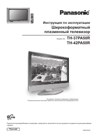
Manual Panasonic TH-37PW5_TH-42PW5


Summary
2 WARNING: To reduce the risk of electric shock, do not remove cover or back.No user-serviceable parts inside. Refer servicing to qualified service personnel. T h e l i g h t n i n g f l a s h w i t harrow-head within a triangleis intended to tell the userthat parts inside the productare a risk of e...
3 Important Safety Instructions 1) Read these instructions. All the safety and operating instructions should be read before the appliance is operated. 2) Keep these instructions. The safety and operating instructions should be retained for future reference. 3) Heed all warnings. All warnings on the ...
4 Table of Contents Important Safety Instructions ...................................... 3 FCC STATEMENT .......................................................... 5 Safety Precautions ........................................................ 6 Accessories ...............................................
Panasonic TVs Manuals
-
 Panasonic 32J330E
User Manual
Panasonic 32J330E
User Manual
-
 Panasonic 55LZ1000E
User Manual
Panasonic 55LZ1000E
User Manual
-
 Panasonic TH-32D400A
User Manual
Panasonic TH-32D400A
User Manual
-
 Panasonic TH-32E400A
User Manual
Panasonic TH-32E400A
User Manual
-
 Panasonic TH-37PA50R_TH-42PA50R
User Manual
Panasonic TH-37PA50R_TH-42PA50R
User Manual
-
 Panasonic TH-40C400A
User Manual
Panasonic TH-40C400A
User Manual
-
 Panasonic TH-40D400A
User Manual
Panasonic TH-40D400A
User Manual
-
 Panasonic TH-40DS610U
User Manual
Panasonic TH-40DS610U
User Manual
-
 Panasonic TH-40E400A
User Manual
Panasonic TH-40E400A
User Manual
-
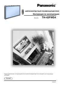 Panasonic TH-42PWD4
Manual
Panasonic TH-42PWD4
Manual
-
 Panasonic TH-43EX600A
User Manual
Panasonic TH-43EX600A
User Manual
-
 Panasonic TH-43GX600A
User Manual
Panasonic TH-43GX600A
User Manual
-
 Panasonic TH-49D400A
User Manual
Panasonic TH-49D400A
User Manual
-
 Panasonic TH-49DX600U
User Manual
Panasonic TH-49DX600U
User Manual
-
 Panasonic TH-49EX600A
User Manual
Panasonic TH-49EX600A
User Manual
-
 Panasonic TH-49GX600A
User Manual
Panasonic TH-49GX600A
User Manual
-
 Panasonic TH-50DS610U
User Manual
Panasonic TH-50DS610U
User Manual
-
 Panasonic TH-50DX700A
User Manual
Panasonic TH-50DX700A
User Manual
-
 Panasonic TH-55CS610A
User Manual
Panasonic TH-55CS610A
User Manual
-
 Panasonic TH-55CS650A
User Manual
Panasonic TH-55CS650A
User Manual