Page 3 - Gas-heated appliances; Safety precautions to take if you smell gas; Open all doors and windows to ventilate the area.; In the UK you must now:; For any gas work in the UK always use a Gas Safe registered engineer.
Gas-heated appliances 3 Safety precautions to take if you smell gas Turn off the gas emergency control valve immediately.This is usually located near the gas meter. Eliminate all sources of ignition in a safe manner.Do not smoke, light cigarette lighters or matches. Do not operate electrical l...
Page 4 - Contents
Contents 4 Warning and Safety instructions ...................................................................... 6 Caring for the environment .............................................................................. 17 Guide to the appliance .......................................................
Page 5 - Converting to another gas type
Contents 5 Installation notes – surface-mounted .................................................................. 42Worktop cutout – surface-mounted .................................................................... 44Spacer bars – surface-mounted.....................................................
Page 6 - Warning and Safety instructions
Warning and Safety instructions 6 This wok complies with all current local and national safety re-quirements. Inappropriate use can, however, lead to personal in-jury and material damage. Read the operating and installation instructions carefully beforeusing the wok. They contain important informati...
Page 7 - Correct application; This wok is designed for domestic use and for use in similar envir-
Warning and Safety instructions 7 Correct application This wok is designed for domestic use and for use in similar envir- onments. This wok is not intended for outdoor use. This wok is intended for domestic use only to cook food and keep it warm. Any other use is not supported by the manufactu...
Page 8 - Safety with children
Warning and Safety instructions 8 Safety with children Children under 8 years of age must be kept away from the wok unless they are constantly supervised. Children aged 8 and older may only use the wok without supervi- sion if they have been shown how to use it in a safe manner. Chil-dren must b...
Page 9 - Technical safety
Warning and Safety instructions 9 Technical safety Unauthorised installation, maintenance and repairs can cause considerable danger for the user. Installation, maintenance and re-pairs must only be carried out by a Miele authorised technician. Damage to the wok can compromise your safety. Check ...
Page 10 - Gas Safe
Warning and Safety instructions 10 For safety reasons, this wok may only be used after it has been built in. This wok must not be used in a non-stationary location (e.g. on a ship). Never open the casing of the wok. Touching or tampering with electrical connections or componentsand mechanical ...
Page 12 - Correct use
Warning and Safety instructions 12 Correct use The wok gets hot when in use and remains hot for some time after being switched off. Do not touch the appliance if there is a possibilitythat it could still be hot. Do not use the wok to heat up the room. Due to the high temperatures radiated, objec...
Page 15 - If you are operating a gas cooking element directly next to the
Warning and Safety instructions 15 If you are operating a gas cooking element directly next to the downdraft extractor, the FlameGuard must be placed between thedowndraft extractor and the element.
Page 16 - Cleaning and care; Do not use a steam cleaning appliance to clean this wok.
Warning and Safety instructions 16 Cleaning and care Do not use a steam cleaning appliance to clean this wok. The steam could reach electrical components and cause a short cir-cuit. Miele will guarantee to supply functional spare parts for a min- imum of 10 years and up to 15 years following the...
Page 17 - Caring for the environment
Caring for the environment 17 Disposal of the packing mater-ial The packaging is designed to protectthe appliance from damage duringtransportation. The packaging materialsused are selected from materials whichare environmentally friendly for disposaland should be recycled. Recycling the packaging re...
Page 18 - Guide to the appliance; Wok; Wok burner
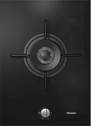
Guide to the appliance 18 Wok a Wok burner b Trivet c Rotary controls
Page 19 - Control knobs
Guide to the appliance 19 Control knobs a Burner off The gas supply is turned off b Strongest flame The outer and inner burners are on the highest setting c Strong flame The outer burner is on the lowest setting, the inner burner on the highest setting d Over-ignition position The outer ...
Page 20 - Burner
Guide to the appliance 20 Burner a b c e f d a Outer burner cap b Inner burner cap c Burner head d Burner base e Thermocouple f Ignition electrode
Page 21 - Accessories supplied; Wok ring
Guide to the appliance 21 Accessories supplied The accessories supplied with your ap-pliance as well as a range of optionalones are available to order from Miele(see “Optional accessories”). Wok ring The wok ring supplied gives additionalstability to the wok, especially to wokswith a rounded base. C...
Page 22 - Before using for the first time
Before using for the first time 22 Please stick the extra data plate forthe appliance supplied with this doc-umentation in the space provided inthe “After sales service” section ofthis booklet. Remove any protective wrapping andstickers. Cleaning the SmartLine ele-ment for the first time Clean...
Page 23 - Pans; Minimum cookware base diameter
Pans 23 Minimum cookware base diameter [cm] Pots/pans 14 Maximum diameter at top of cook- ware [cm] Pots/pans 30 - Observe the dimensions given in the chart. Using pans that are too largecan cause the flames to spread outand damage the surrounding worktopor other appliances. Using pans ofthe correct...
Page 25 - Operation; Switching on; Risk of fire with overheated food.; FlameGuard
Operation 25 Switching on If you are operating a gas cookingelement next to a downdraft ex-tractor, this will affect the gas cook-ing element's function.Place the FlameGuard between thegas cooking element and thedowndraft extractor. Risk of fire with overheated food. Unattended food can overheat a...
Page 26 - Adjusting the flame
Operation 26 Adjusting the flame As the outer part of the flame is muchhotter than the centre, the tips of theflames should stay beneath the panbase. Flame tips which extend beyondthe sides of the pan merely warm upthe air in the room and can also dam-age pan handles and increase the riskof injury. ...
Page 27 - Tips on saving energy; - Use a pan lid whenever possible to
Tips on saving energy 27 - Use a pan lid whenever possible to minimize heat loss. - Wide, shallow pans are preferable to tall, narrow ones. They will heat upfaster. - Cook with as little water as possible. - Reduce the size of the flame once the water has come to the boil or the oilis hot enough to ...
Page 28 - Safety features; position, the burner is ready
Safety features 28 Thermo-electric flame failuremonitor Your wok is equipped with a thermo-electric flame failure monitor. If a gasflame is extinguished, e.g. by food boil-ing over or by a draught, the gas supplyis switched off. This prevents the re-lease of gas. If you turn the rotary con-trol to t...
Page 29 - Unsuitable cleaning agents
Cleaning and care 29 Danger of burning due to hot surfaces.The surfaces will be hot after cook-ing.Switch the wok off.Allow the surfaces to cool down be-fore cleaning the wok. Risk of damage due to moisture ingress.The steam from a steam cleaning ap-pliance could reach live electricalcomponents ...
Page 30 - Cleaning the ceramic surface; Spots
Cleaning and care 30 Cleaning the ceramic surface Risk of damage by pointed ob- jects.The seal between the SmartLine ele-ment and the worktop could sufferdamage.Do not use pointed objects for clean-ing. Not all soiling and residues can beremoved using a solution of wash-ing-up liquid.An invisible ...
Page 31 - Cleaning the rotary controls
Cleaning and care 31 Cleaning the rotary controls Clean the rotary control(s) using asolution of warm water and a littlewashing-up liquid applied with a softsponge. Soften any stubborn soilingbeforehand. Dry the control(s) with a clean cloth. Cleaning the trivets Remove the trivets. Clean th...
Page 32 - Cleaning the burners; Assembling the burners
Cleaning and care 32 Cleaning the burners Do not clean any parts of the burnersin a dishwasher. The surface of the burner cap will be-come duller with time. This is com-pletely normal and does not indicatematerial deterioration. The burner should be dismantled andthen cleaned by hand using a solu-...
Page 33 - Problem solving guide; Problem
Problem solving guide 33 Many malfunctions and faults that can occur in daily operation can be easilyremedied. Time and money will be saved because a service call will not beneeded. The following guide may help you to find the reason for a malfunction or a fault,and to correct it. Problem Cause and ...
Page 35 - Optional accessories; Removes finger marks and light soiling
Optional accessories 35 Miele offer a comprehensive range ofuseful accessories as well as cleaningand conditioning products for yourMiele appliances. These products can be ordered throughthe Miele Webshop. They can also be ordered from Miele(see end of this booklet for contact de-tails) or from your...
Page 36 - After sales service; Contact in the event of a fault
After sales service 36 Contact in the event of a fault In the event of any faults which you cannot remedy yourself, please contact yourMiele dealer or the Miele Customer Service Department. You can book a Miele Customer Service Department call-out online atwww.miele.com/service. Contact information ...
Page 37 - Installation; Safety instructions for installation; Damage risk from incorrect installation.
Installation *INSTALLATION* 37 Safety instructions for installation Damage risk from incorrect installation. Incorrect installation can cause damage to the SmartLine element.The SmartLine element must only be installed by a qualified person. Damage from falling objects. Take care not to damage t...
Page 38 - Observe carefully the safety clearances listed on the following
Installation *INSTALLATION* 38 Observe carefully the safety clearances listed on the following pages.
Page 39 - Safety distances
Installation *INSTALLATION* 39 Safety distances Safety distance above the SmartLineelement The safety distance specified by themanufacturer of the cooker hood mustbe maintained between the SmartLineelement and the cooker hood above it. If combustible objects are installedabove the SmartLine element ...
Page 40 - back
Installation *INSTALLATION* 40 Safety distances to the sides andback of the appliance The SmartLine element should prefer-ably be installed with plenty of space onthe right and left. The minimum distance specified be- low must be observed between the rearof the SmartLine element and a tall unitor...
Page 41 - Flush-fit installation
Installation *INSTALLATION* 41 Safety distance when installing the appliance near a wall with additionalniche cladding If a niche cladding is installed, a minimum safety distance must be maintainedbetween the worktop cut-out and the cladding, since high temperatures can dam-age these materials. If t...
Page 42 - Tiled worktop
Installation *INSTALLATION* 42 Installation notes – surface-mounted Sealing between the SmartLine Ele-ment and the worktop The SmartLine element and worktopmay be damaged if the elementneeds to be removed after it hasbeen sealed with a sealant.Do not use any sealant between theSmartLine element and ...
Page 44 - Worktop cutout – surface-mounted
Installation *INSTALLATION* 44 Worktop cutout – surface-mounted
Page 45 - Installation with a countertop extractor
Installation *INSTALLATION* 45 Installation with a countertop extractor Combination examples Number x width [mm] Dimen- sion B [mm] Cooking ele- ments Countertop extractor 1 x 378 1 x 120 481 2 x 378 1 x 120 862 1 x 3781 x 620 2 x 120 1226 3 x 378 2 x 120 1365 2 x 3781 x 620 2 x 120 1607 4 x 378 2 x...
Page 46 - Installation without a countertop extractor
Installation *INSTALLATION* 46 Installation without a countertop extractor Combination examples Number x width [mm] Dimension B [mm] Cooking elements 1 x 378 359 2 x 378 740 1 x 3781 x 620 982 3 x 378 1121 2 x 3781 x 620 1363 4 x 378 1502 2 x 3781 x 800 1554 2 x 3781 x 936 1680
Page 47 - Spacer bars – surface-mounted; Installing 3 elements and 2 spacer bars
Installation *INSTALLATION* 47 Spacer bars – surface-mounted If you are installing several appliances, you must fit spacer bars between them. The clips supplied with the spacer bars are only required for installing aCSDA 700x FL. Installing 3 elements and 2 spacer bars
Page 48 - Installation dimensions – Surface-mounted; All dimensions are given in mm.
Installation *INSTALLATION* 48 Installation dimensions – Surface-mounted All dimensions are given in mm. a Front b Mains connection box with mains connection cableMains connection cable L = 1440 mm c Gas connection R ½ " ISO 7-1 (DIN EN 10226)
Page 49 - Installation – surface-mounted; Seal any cut surfaces on
Installation *INSTALLATION* 49 Installation – surface-mounted Preparing the worktop Create the worktop cutout. Remem-ber to maintain the minimum safetydistances (see “Installation – Safetydistances”). Seal any cut surfaces on wooden worktops with a special varnish, sil- icone sealant or resin to...
Page 50 - Installing the SmartLine element
Installation *INSTALLATION* 50 Installing the SmartLine element Stick the supplied sealing strip underthe edge of the SmartLine element.Do not apply the sealing strip undertension. Feed the mains connection cabledown through the worktop cutout. Position the SmartLine element in theworktop cuto...
Page 51 - Natural stone worktops
Installation *INSTALLATION* 51 Installation notes – flush-fit Flush-fit installation is only possible innatural stone (granite, marble), solidwood and tiled worktops. For installa-tion in worktops made of other materi-als, please consult the relevant manu-facturer as to whether their worktopsare sui...
Page 53 - Worktop cutout – flush-fit; Natural stone worktop
Installation *INSTALLATION* 53 Worktop cutout – flush-fit B 0 50 A 524 50 0 + 1 + 1 ß R 4 B A 0 2 12 0 1 0 5,5 + 0,5 * / 7 + 0,5 0 2 12 0 1 0 5,5 + 0,5 * / 7 + 0,5 + 1 + 1 + 1 + 1 B A + 1 + 1 Natural stone worktop Wooden worktop * 7 + 0.5 mm with CS 7611 FL
Page 56 - Spacer bars – flush-fit
Installation *INSTALLATION* 56 Spacer bars – flush-fit If you are installing several appliances, you must fit spacer bars between them. The clips supplied with the spacer bars are only required for installing aCSDA 700x FL. Installing 3 elements and 2 spacer bars
Page 57 - Installation dimensions – Flush-fit
Installation *INSTALLATION* 57 Installation dimensions – Flush-fit All dimensions are given in mm. a Front b Mains connection box with mains connection cableMains connection cable L = 1440 mm c Stepped cutout (for detailed illustrations, see “Installation – Worktop cutout –flush-fit”) d 12 mm wooden...
Page 58 - Installation – flush-fit
Installation *INSTALLATION* 58 Installation – flush-fit Preparing the worktop Create the worktop cutout. Remem-ber to maintain the minimum safetydistances (see “Installation – Safetydistances”). Seal any cut surfaces on wooden worktops with a special varnish, sil- icone sealant or resin to preve...
Page 60 - Gas connection; Risk of explosion due to an in-
Installation *INSTALLATION* 60 Gas connection For any gas work in the UK alwaysuse a Gas Safe registered engineer. Risk of explosion due to an in- correct gas connection.If the gas connection is carried outincorrectly, it may result in gas leak-age.Connection to the gas supply mustonly be undertak...
Page 61 - Risk of explosion due to dam-
Installation *INSTALLATION* 61 Risk of heat damage. Gas connections, pipes and connec-tion cables can suffer damage if ex-posed to heat from the hob.After installation make sure thatneither the gas pipe nor the mainscable can come into contact with hotparts of the appliance and that thegas pipe an...
Page 62 - Using a 90° angle
Installation *INSTALLATION* 62 Using a 90° angle a Connection R ¹/₂" with test point -ISO 7-1 (DIN EN 10226) b 90° elbowThe installation height in the area ofthe gas connection is increased toapprox. 90 mm.
Page 63 - Burner ratings; Natural gas H
Installation *INSTALLATION* 63 Burner ratings Nominal ratings Gas type Highest setting Lowest setting kW g/h kW Natural gas H 4.5 – 0.3 Liquid gas 4.2 306 0.3
Page 64 - Electrical connection; Risk of fire from overheating.
Installation *INSTALLATION* 64 Electrical connection The SmartLine element is supplied witha mains cable with moulded plug readyfor connection to a suitable earthedsocket. The socket must be easily accessibleafter the SmartLine element has beeninstalled. If the socket is not easily ac-cessible, ensu...
Page 65 - Jet table; Changing the jets; and
Converting to another gas type *INSTALLATION* 65 Risk of explosion due to an in- correct conversion.If the conversion to another type ofgas is carried out incorrectly, it mayresult in gas leakage.Conversion from one type of gas toanother must only be undertaken byan approved and registered gas in-...
Page 66 - Changing the main jets
Converting to another gas type *INSTALLATION* 66 Changing the main jets Remove the burner caps and burner head . Using an M7 socket spanner, un-screw the main jets . Fit the correct jets securely (see jettable). Secure the jets against inadvertentloosening with sealing wax. Changin...
Page 67 - Functional check; Check all gas fittings for leaks.
Converting to another gas type *INSTALLATION* 67 Fit the correct jets securely (see jettable). Secure the jets against inadvertentloosening with sealing wax. Functional check Check all gas fittings for leaks. Reassemble the hob. Ignite all burners to check that theyare operating correctly....
Page 68 - Product data sheets; Information for domestic gas-fired hobs
Product data sheets 68 The following data sheets apply to the models described in this operating instruc-tion manual. Information for domestic gas-fired hobs In acc. with regulation (EU) No. 66/2014 MIELE Model name/identifier CS 7101-1 Number of gas burners 1 Energy efficiency per gas burner (EE ga...


 Miele APCL 043
User Manual
Miele APCL 043
User Manual
 Miele APWM 065
Installation Manual
Miele APWM 065
Installation Manual
 Miele APWM 070
Installation Manual
Miele APWM 070
Installation Manual
 Miele SC
Installation Manual
Miele SC
Installation Manual
 Miele PR
Installation Manual
Miele PR
Installation Manual
 Miele APCL 047
User Manual
Miele APCL 047
User Manual
 Miele PLW 8505
Installation Manual
Miele PLW 8505
Installation Manual
![Miele PT 7186 Vario [EL]](https://manualsarea.com/img/product/thumbs/180/69/3e/693e1219f5c0d53fde982888bd54a3ec.webp) Miele PT 7186 Vario [EL]
User Manual
Miele PT 7186 Vario [EL]
User Manual
 Miele CM/1
User Manual
Miele CM/1
User Manual
![Miele PLW 8617 [EL/S TH]](https://manualsarea.com/img/product/thumbs/180/fe/90/fe9010c5f8c3c4aada5d83b417c78507.webp) Miele PLW 8617 [EL/S TH]
Installation Manual
Miele PLW 8617 [EL/S TH]
Installation Manual
![Miele PWM 908 [EL DP MAR 3 AC 400-480V 50-60Hz]](https://manualsarea.com/img/product/thumbs/180/20/e5/20e5e929bcb336fc6b2f128d9c857a3d.webp) Miele PWM 908 [EL DP MAR 3 AC 400-480V 50-60Hz]
User Manual
Miele PWM 908 [EL DP MAR 3 AC 400-480V 50-60Hz]
User Manual
![Miele PWM 906 [EL DP MAR 3 AC 400-480V 50-60Hz]](https://manualsarea.com/img/product/thumbs/180/57/c8/57c81dd8d0abe05852b709a3fa9b80db.webp) Miele PWM 906 [EL DP MAR 3 AC 400-480V 50-60Hz]
Installation Manual
Miele PWM 906 [EL DP MAR 3 AC 400-480V 50-60Hz]
Installation Manual
![Miele PWM 906 [EL DP MAR 2N AC 400V 50-60Hz]](https://manualsarea.com/img/product/thumbs/180/ce/23/ce232ceeda728532882a2a2f56bf2abc.webp) Miele PWM 906 [EL DP MAR 2N AC 400V 50-60Hz]
User Manual
Miele PWM 906 [EL DP MAR 2N AC 400V 50-60Hz]
User Manual
![Miele PLW 8617 [EL TH]](https://manualsarea.com/img/product/thumbs/180/e8/4a/e84a63b24dca64279b26bca714985678.webp) Miele PLW 8617 [EL TH]
User Manual
Miele PLW 8617 [EL TH]
User Manual
![Miele PDR 908 [EL MAR 3N AC 400V 50-60Hz]](https://manualsarea.com/img/product/thumbs/180/05/b7/05b705998b251f92b271e908423e1ecb.webp) Miele PDR 908 [EL MAR 3N AC 400V 50-60Hz]
Installation Manual
Miele PDR 908 [EL MAR 3N AC 400V 50-60Hz]
Installation Manual
![Miele PLW 8615 [EL CT]](https://manualsarea.com/img/product/thumbs/180/70/ff/70ff37b9174e78db8d00ddce8cf08ee3.webp) Miele PLW 8615 [EL CT]
Installation Manual
Miele PLW 8615 [EL CT]
Installation Manual
![Miele PLW 8616 [EL/S]](https://manualsarea.com/img/product/thumbs/180/37/f4/37f4255dee3c9942a13241f3ccd5fe93.webp) Miele PLW 8616 [EL/S]
Installation Manual
Miele PLW 8616 [EL/S]
Installation Manual
![Miele PWM 916 [EL DV DD SOM]](https://manualsarea.com/img/product/thumbs/180/21/65/21657a907bb735f3acf5a7bdbbc78c8a.webp) Miele PWM 916 [EL DV DD SOM]
Manual
Miele PWM 916 [EL DV DD SOM]
Manual
![Miele PFD 104 SCVi XXL [120V]](https://manualsarea.com/img/product/thumbs/180/0a/20/0a20c04430aaa9be6a985688f5bb5580.webp) Miele PFD 104 SCVi XXL [120V]
Installation Manual
Miele PFD 104 SCVi XXL [120V]
Installation Manual
![Miele PDR 507 HP [MAR]](https://manualsarea.com/img/product/thumbs/180/58/9e/589e9ba94b88174fa0cdb27b4bbaac5b.webp) Miele PDR 507 HP [MAR]
User Manual
Miele PDR 507 HP [MAR]
User Manual