Makita GPK01M1 - Manuals
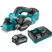
User Manual Makita GPK01M1


Summary
2 ENGLISH ENGLISH (Original instructions) SPECIFICATIONS Model: GPK01 Planing width 82 mm (3-1/4") Planing depth 4 mm (5/32") Shiplapping depth 25 mm (1") No load speed 15,000 /min Overall length (with BL4040) 385 mm (15-1/8") Rated voltage D.C. 36 V - 40 V max Net weight 3.7 - 4.9 k...
4 ENGLISH 3. Follow instruction for lubricating and chang- ing accessories. 4. Do not modify or attempt to repair the appli- ance or the battery pack except as indicated in the instructions for use and care. Cordless Planer Safety Warnings 1. Wait for the cutter to stop before setting the tool down....
5 ENGLISH 11. When disposing the battery cartridge, remove it from the tool and dispose of it in a safe place. Follow your local regulations relating to disposal of battery. 12. Use the batteries only with the products specified by Makita. Installing the batteries to non-compliant products may resul...
Makita Electric Planers Manuals
-
 Makita 1002BA
User Manual
Makita 1002BA
User Manual
-
Makita 1002BA
Manual
-
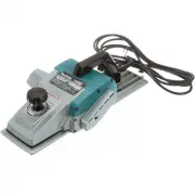 Makita 1806B
User Manual
Makita 1806B
User Manual
-
Makita 1806B
Manual
-
 Makita 1911B
User Manual
Makita 1911B
User Manual
-
Makita 1911B
Manual
-
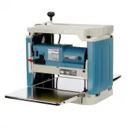 Makita 2012NB
User Manual
Makita 2012NB
User Manual
-
Makita 2012NB
Manual
-
 Makita DKP180Z
User Manual
Makita DKP180Z
User Manual
-
 Makita GA9060RX3
User Manual
Makita GA9060RX3
User Manual
-
 Makita GPK01Z
User Manual
Makita GPK01Z
User Manual
-
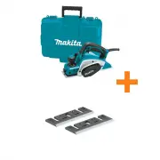
 Makita KP0800
User Manual
Makita KP0800
User Manual
-
Makita KP0800
Manual
-
 Makita KP0800K
User Manual
Makita KP0800K
User Manual
-
Makita KP0800K
Manual
-
 Makita KP0800K-D-46230
User Manual
Makita KP0800K-D-46230
User Manual
-
 Makita KP0800X1
User Manual
Makita KP0800X1
User Manual
-
 Makita KP0810
Manual
Makita KP0810
Manual
-
 Makita KP0810C
User Manual
Makita KP0810C
User Manual
-
Makita KP0810C
Manual