Makita GDT02D - Manuals
User Manual Makita GDT02D


Summary
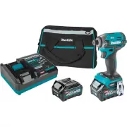
2 ENGLISH ENGLISH (Original instructions) SPECIFICATIONS Model: GDT02 Fastening capacities Machine screw M4 - M8 (5/32" - 5/16") Standard bolt M5 - M16 (3/16" - 5/8") High tensile bolt M5 - M14 (3/16" - 9/16") No load speed (RPM) 4 (Max impact mode) 0 - 3,700 /min 3 (Hard imp...
4 ENGLISH 4. Under abusive conditions, liquid may be ejected from the battery; avoid contact. If con- tact accidentally occurs, flush with water. If liquid contacts eyes, additionally seek medical help. Liquid ejected from the battery may cause irritation or burns. 5. Do not use a battery pack or to...
5 ENGLISH 10. The contained lithium-ion batteries are subject to the Dangerous Goods Legislation requirements. For commercial transports e.g. by third parties, forwarding agents, special requirement on pack- aging and labeling must be observed. For preparation of the item being shipped, consult- ing...
Makita Impact Drivers Manuals
-
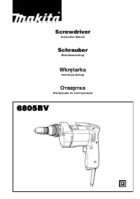 Makita 6805BV
User Manual
Makita 6805BV
User Manual
-
Makita 6805BV
Manual
-
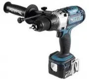
 Makita BDF 460 SJE
User Manual
Makita BDF 460 SJE
User Manual
-
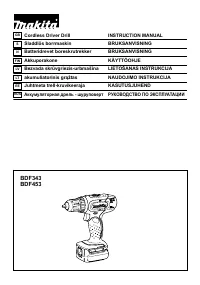 Makita BDF453SHE
User Manual
Makita BDF453SHE
User Manual
-
 Makita BHP 441 RFE
User Manual
Makita BHP 441 RFE
User Manual
-
 Makita BTD136RFE
User Manual
Makita BTD136RFE
User Manual
-
 Makita BTD136Z
User Manual
Makita BTD136Z
User Manual
-
 Makita BTP131RFE
User Manual
Makita BTP131RFE
User Manual
-
 Makita BTP131Z
User Manual
Makita BTP131Z
User Manual
-
 Makita BTP141RFE
User Manual
Makita BTP141RFE
User Manual
-
 Makita BTP141Z
User Manual
Makita BTP141Z
User Manual
-
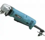 Makita DA3010F
User Manual
Makita DA3010F
User Manual
-
Makita DA3010F
Manual
-
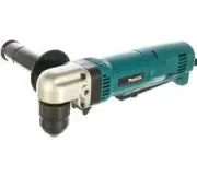 Makita DA3011F
User Manual
Makita DA3011F
User Manual
-
Makita DA3011F
Manual
-
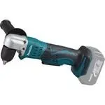 Makita DDA351Z
User Manual
Makita DDA351Z
User Manual
-
 Makita DDA450ZK
User Manual
Makita DDA450ZK
User Manual
-
 Makita DDA460Z
User Manual
Makita DDA460Z
User Manual
-
 Makita DDF 481 RT3J
User Manual
Makita DDF 481 RT3J
User Manual
-
 Makita DDF083RFE
User Manual
Makita DDF083RFE
User Manual