Makita GDT01D - Manuals

User Manual Makita GDT01D


Summary
2 ENGLISH ENGLISH (Original instructions) SPECIFICATIONS Model: GDT01 Fastening capacities Machine screw 4 mm - 8 mm (5/32" - 5/16") Standard bolt 5 mm - 16 mm (3/16" - 5/8") High tensile bolt 5 mm - 14 mm (3/16" - 9/16") No load speed (RPM) 4 (Max impact mode) 0 - 3,700 /min...
3 ENGLISH SAFETY WARNINGS General power tool safety warnings WARNING: Read all safety warnings, instruc- tions, illustrations and specifications provided with this power tool. Failure to follow all instructions listed below may result in electric shock, fire and/or serious injury. Save all warnings ...
4 ENGLISH 5. Maintain power tools and accessories. Check for misalignment or binding of moving parts, breakage of parts and any other condition that may affect the power tool’s operation. If dam - aged, have the power tool repaired before use. Many accidents are caused by poorly maintained power too...
Makita Impact Drivers Manuals
-
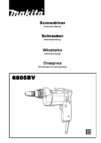 Makita 6805BV
User Manual
Makita 6805BV
User Manual
-
Makita 6805BV
Manual
-
 Makita BDF 460 SJE
User Manual
Makita BDF 460 SJE
User Manual
-
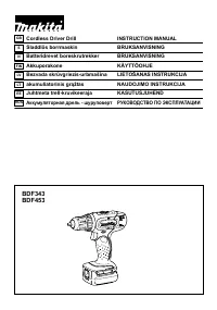 Makita BDF453SHE
User Manual
Makita BDF453SHE
User Manual
-
 Makita BHP 441 RFE
User Manual
Makita BHP 441 RFE
User Manual
-
 Makita BTD136RFE
User Manual
Makita BTD136RFE
User Manual
-
 Makita BTD136Z
User Manual
Makita BTD136Z
User Manual
-
 Makita BTP131RFE
User Manual
Makita BTP131RFE
User Manual
-
 Makita BTP131Z
User Manual
Makita BTP131Z
User Manual
-
 Makita BTP141RFE
User Manual
Makita BTP141RFE
User Manual
-
 Makita BTP141Z
User Manual
Makita BTP141Z
User Manual
-
 Makita DA3010F
User Manual
Makita DA3010F
User Manual
-
Makita DA3010F
Manual
-
 Makita DA3011F
User Manual
Makita DA3011F
User Manual
-
Makita DA3011F
Manual
-
 Makita DDA351Z
User Manual
Makita DDA351Z
User Manual
-
 Makita DDA450ZK
User Manual
Makita DDA450ZK
User Manual
-
 Makita DDA460Z
User Manual
Makita DDA460Z
User Manual
-
 Makita DDF 481 RT3J
User Manual
Makita DDF 481 RT3J
User Manual
-
 Makita DDF083RFE
User Manual
Makita DDF083RFE
User Manual