Page 2 - ENGLISH; SPECIFICATIONS; Read and understand all instructions.; SAVE THESE INSTRUCTIONS; Work Area; Electrical Safety
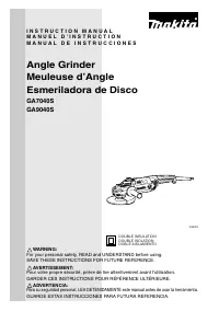
2 ENGLISH SPECIFICATIONS • Due to our continuing programme of research and development, the specifications herein are subject to change without notice. • Note: Specifications may differ from country to country. GENERAL SAFETY RULES USA002-2 (For All Tools) WARNING: Read and understand all instructio...
Page 3 - SPECIFIC SAFETY RULES
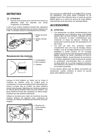
3 hearing protection must be used for appropriate con-ditions. Ordinary eye or sun glasses are NOT eyeprotection. Tool Use and Care 15. Use clamps or other practical way to secure and support the workpiece to a stable platform. Hold- ing the work by hand or against your body is unsta-ble and may lea...
Page 4 - FUNCTIONAL DESCRIPTION; Shaft lock
4 wheel immediately. Run the tool (with guard) atno load for about a minute, holding tool awayfrom others. If wheel is flawed, it will likely sepa-rate during this test. 7. Use only flanges specified for this tool. 8. Be careful not to damage the spindle, the flange(especially the installing surface...
Page 5 - Switch action; ASSEMBLY; Installing or removing wheel guard
5 The switch handle can be rotated to either 90° left or rightto fit your work needs. First, unplug the tool. Press thelock button and rotate the switch handle to left or rightfully. The switch handle will be locked in that position. CAUTION: • Always make sure that the switch handle is lockedin the...
Page 6 - OPERATION
6 Loosen the lever on the wheel guard. Mount the wheelguard with the protrusion on the wheel guard bandaligned with the notch on the bearing box. Then rotatethe wheel guard around to the position shown in the fig-ure. Tighten the lever to fasten the wheel guard. If thelever is too tight or too loose...
Page 7 - Grinding and sanding operation
7 • NEVER bang or hit grinding disc or wheel ontowork. • Avoid bouncing and snagging the wheel, especiallywhen working corners, sharp edges etc. This cancause loss of control and kickback. • NEVER use tool with wood cutting blades and othersawblades. Such blades when used on a grinderfrequently kick...
Page 8 - MAINTENANCE; Replacing carbon brushes; ACCESSORIES
8 MAINTENANCE CAUTION: • Always be sure that the tool is switched off andunplugged before attempting to perform inspectionor maintenance. The tool and its air vents have to be kept clean. Regularlyclean the tool’s air vents or whenever the vents start tobecome obstructed. Replacing carbon brushes Wh...
Page 10 - MAKITA LIMITED ONE YEAR WARRANTY
10 EN0006-1 MAKITA LIMITED ONE YEAR WARRANTY Warranty Policy Every Makita tool is thoroughly inspected and testedbefore leaving the factory. It is warranted to be free ofdefects from workmanship and materials for the period ofONE YEAR from the date of original purchase. Shouldany trouble develop dur...
Page 11 - FRANÇAIS; SPÉCIFICATIONS; (Pour tous les outils
11 FRANÇAIS SPÉCIFICATIONS • Le fabricant se réserve le droit de modifier sans avertissement les spécifications. • Note: Les spécifications peuvent varier selon les pays. RÈGLES DE SÉCURITÉ GÉNÉRALES USA002-2 (Pour tous les outils ) AVERTISSEMENT: Vous devez lire et comprendre toutes lesinstructions...
Page 14 - SYMBOLES; Blocage de l’arbre
14 SYMBOLES USD201-2 Les symboles utilisés pour l’outil sont présentés ci-dessous. V ............................ volts A ........................... ampères Hz .......................... hertz .................... courant alternatif ....................... vitesse à vide ....................... con...
Page 15 - ASSEMBLAGE; Installation de la poignée latérale (poignée)
15 NOTE: Les modèles GA7040S et GA9040S se mettent à tournerlentement lors de leur mise sous tension. Cette fonctionde démarrage en douceur facilite l’utilisation. ASSEMBLAGE ATTENTION: • Avant d’effectuer toute intervention sur l’outil,assurez-vous toujours qu’il est hors tension etdébranché. Insta...
Page 16 - UTILISATION; Opérations de meulage et de ponçage
16 Pour serrer le contre-écrou, appuyez fermement sur leblocage de l’arbre pour empêcher l’arbre de tourner, puisutilisez la clé à contre-écrou en serrant fermement dansle sens des aiguilles d’une montre. Pour retirer la meule, suivez la procédure de l’installationde l’autre côté. Installation ou re...
Page 18 - ENTRETIEN; Remplacement des charbons; ACCESSOIRES
18 ENTRETIEN ATTENTION: • Assurez-vous toujours que l’outil est hors tension etdébranché avant d’y effectuer tout travaild’inspection ou d’entretien. L’outil et ses orifices d’aération doivent être maintenuspropres. Nettoyez régulièrement les orifices d’aération del’outil, ou chaque fois qu’ils comm...
Page 20 - GARANTIE LIMITÉE D’UN AN MAKITA
20 EN0006-1 GARANTIE LIMITÉE D’UN AN MAKITA Politique de garantie Chaque outil Makita est inspecté rigoureusement et testéavant sa sortie d’usine. Nous garantissons qu’il seraexempt de défaut de fabrication et de vice de matériaupour une période d’UN AN à partir de la date de sonachat initial. Si un...
Page 21 - ESPAÑOL; ESPECIFICACIONES; Lea y entienda todas las instrucciones.
21 ESPAÑOL ESPECIFICACIONES • Debido a un programa continuo de investigación y desarrollo, las especificaciones aquí dadas están sujetas a cambios sin previo aviso. • Nota: Las especificaciones pueden ser diferentes de país a país. NORMAS DE SEGURIDAD GENERALES USA002-2 (Para todas las herramientas)...
Page 24 - SÍMBOLOS; Bloqueo del eje
24 cuero y delantales de taller para proteger la pielcontra el contacto con virutas calientes. 20. La utilización de esta herramienta para amolar o pulir algunos productos, pinturas y maderapodrá exponer al usuario a polvo que contengasustancias peligrosas. Utilice protecciónrespiratoria apropiada. ...
Page 25 - MONTAJE; Instalación de la empuñadura lateral (mango)
25 PRECAUCIÓN: • Antes de conectar la herramienta, compruebesiempre que el gatillo interruptor se accionadebidamente y que vuelve a la posición “OFF”(apagado) cuando lo suelta. • El interruptor puede ser bloqueado en la posición“ON” (encendido) para mayor comodidad deloperario durante una utilizació...
Page 27 - OPERACIÓN; Operación de amolado y lijado
27 OPERACIÓN AVISO: • No deberá ser nunca necesario forzar laherramienta. El peso de la herramienta aplica lapresión adecuada . El forzamiento y la presiónexcesivos podrán ocasionar una peligrosa roturadel disco. • Reemplace el disco SIEMPRE si deja caer laherramienta durante el amolado. • No lance ...
Page 28 - MANTENIMIENTO; Reemplazamiento de las escobillas de carbón; ACCESORIOS
28 posibilidad de heridas causadas por el contactocon alambres rotos. • Utilice SIEMPRE el protector de disco con discosde cepillo de alambres, asegurándose de que eldisco encaje dentro del protector. El disco puededesintegrarse durante la utilización y el protectorayuda a reducir las posibilidades ...
Page 30 - GARANTÍA LIMITADA MAKITA DE UN AÑO
30 EN0006-1 GARANTÍA LIMITADA MAKITA DE UN AÑO Política de garantía Cada herramienta Makita es inspeccionada y probadaexhaustivamente antes de salir de fábrica. Se garantizaque va a estar libre de defectos de mano de obra ymateriales por el periodo de UN AÑO a partir de la fechade adquisición origin...
Page 32 - Makita Corporation of America
WARNING Some dust created by power sanding, sawing, grinding, drilling, and otherconstruction activities contains chemicals known to the State of Californiato cause cancer, birth defects or other reproductive harm. Some examplesof these chemicals are:• lead from lead-based paints, • crystalline sili...