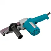
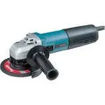
Makita 9558HN - Manuals

Makita 9558HN Grinding Machine – User Manual, Manual in PDF format online.
Manuals:
User Manual Makita 9558HN


Summary
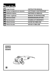
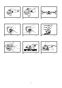
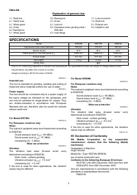
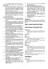
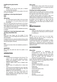
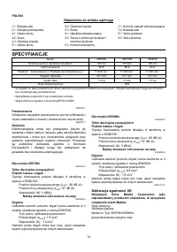
3 ENGLISH Explanation of general view 1-1. Shaft lock 2-1. Switch lever 4-1. Wheel guard 4-2. Screw 4-3. Bearing box 5-1. Wheel guard 5-2. Bearing box 5-3. Screw 6-1. Lock nut 6-2. Depressed center grinding wheel / Multi-disc 6-3. Inner flange 7-1. Lock nut wrench 7-2. Shaft lock 9-1. Exhaust vent 9...
4 The technical documentation is kept by our authorised representative in Europe who is: Makita International Europe Ltd, Michigan, Drive, Tongwell, Milton Keynes, MK15 8JD, England 30th January 2009 000230 Tomoyasu Kato Director Makita Corporation 3-11-8, Sumiyoshi-cho, Anjo, Aichi, JAPAN GEB033-2 ...
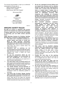
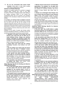
6 cause snagging, tearing of the disc or kickback. Safety Warnings Specific for Wire Brushing Operations: a) Be aware that wire bristles are thrown by the brush even during ordinary operation. Do not overstress the wires by applying excessive load to the brush. The wire bristles can easily penetrate...
Manual Makita 9558HN


Summary
P 2 / 8 R epair CAUTION: Disconnect the machine and remove the wheel for safety before repair/maintenance! Fig. 1 Carbon brush (2 pcs) 1) Remove 4x18 Tapping screw and separate Rear cover from Motor housing. Then remove Carbon brushes. ( Fig. 1 ) 2) Unscrew four 4x30 Tapping screws and remove the as...
P 3 / 8 R epair Fig. 4 Fig. 5 Fig. 6 Fig. 7 Fig. 8 [3] -1. Armature and Small Spiral Bevel Gear (cont.) Do the reverse of the disassembling steps.Note: Use arbor press and Bearing Setting Plate (of proper size ) when fitting Ball bearing 629LLB in Gear housing cover. (Fig. 4)Important: Assemble Gear...
C ircuit diagram P 5 / 8 RedClear Color index of lead wires' sheath Black Brush holder A Brush holder A Noise suppressor* Earth terminal (Ground terminal)on the lead wire of Noise suppressor Power supplycord Brush holder B Brush holder B Field Switch *Some countries do not use noise suppressor
Makita Grinding Machines Manuals
-
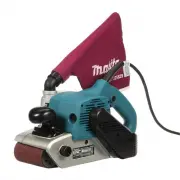
 Makita 9031
User Manual
Makita 9031
User Manual
-
Makita 9031
Manual
-
 Makita 9032
User Manual
Makita 9032
User Manual
-
Makita 9032
Manual
-
 Makita 9403
User Manual
Makita 9403
User Manual
-
Makita 9403
Manual
-
 Makita 9404
User Manual
Makita 9404
User Manual
-
Makita 9404
Manual
-
 Makita 9903
User Manual
Makita 9903
User Manual
-
Makita 9903
Manual
-
 Makita 9920
User Manual
Makita 9920
User Manual
-
Makita 9920
Manual
-
 Makita 9565CVK
User Manual
Makita 9565CVK
User Manual
-
 Makita 9924DB
User Manual
Makita 9924DB
User Manual
-
Makita 9924DB
Manual
-
 Makita BO3710
User Manual
Makita BO3710
User Manual
-
 Makita BO3711
User Manual
Makita BO3711
User Manual
-
 Makita BO4556
User Manual
Makita BO4556
User Manual
-
Makita BO4556
Manual
-
 Makita BO4556K
User Manual
Makita BO4556K
User Manual