JVC KD-AVX1 - Manuals
JVC KD-AVX1 Car Radio – Manual in PDF format online.
Manuals:
Manual JVC KD-AVX1


Summary
1-2 (No.MA165) SPECIFICATION for NORTHERN AMERICA version AUDIO AMPLIFIER SECTION Power Output 20 W RMS × 4 Channels at 4 Ω and [< or =] 1% THD+N Signal to Noise Ratio 80 dBA (reference: 1 W into 4 Ω ) Load Impedance 4 Ω (4 Ω to 8 Ω allowance) Equalizer Control Range Frequencies 60 Hz, 150 Hz, 40...
(No.MA165)1-3 for EUROPE version AUDIO AMPLIFIER SECTION Maximum Power Output Front 50 W per channel Rear 50 W per channel Continuous Power Output (RMS) Front 20 W per channel into 4 Ω , 40 Hz to 20 000 Hz at no more than 0.8% total harmonic distortion. Rear 20 W per channel into 4 Ω , 40 Hz to 20 0...
1-4 (No.MA165) for ASIA & AUSTRALIA version Design and specifications are subject to change without notice. AUDIO AMPLIFIER SECTION Maximum Power Output Front 50 W per channel Rear 50 W per channel Continuous Power Output (RMS) Front 20 W per channel into 4 Ω , 40 Hz to 20 000 Hz at no more than...
JVC Car Radios Manuals
-
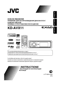 JVC KD-AVX11
User Manual
JVC KD-AVX11
User Manual
-
JVC KD-AVX11
Manual
-
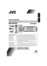 JVC KD-AVX2
User Manual
JVC KD-AVX2
User Manual
-
JVC KD-AVX2
Manual
-
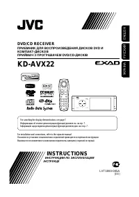 JVC KD-AVX22
User Manual
JVC KD-AVX22
User Manual
-
JVC KD-AVX22
Manual
-
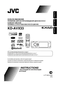 JVC KD-AVX33
User Manual
JVC KD-AVX33
User Manual
-
JVC KD-AVX33
Manual
-
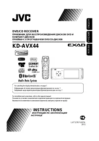 JVC KD-AVX44
User Manual
JVC KD-AVX44
User Manual
-
 JVC KD-AVX55
User Manual
JVC KD-AVX55
User Manual
-
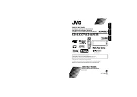
 JVC KD-AVX77
User Manual
JVC KD-AVX77
User Manual
-
JVC KD-AVX77
Manual
-
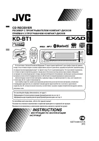 JVC KD-BT1
User Manual
JVC KD-BT1
User Manual
-
JVC KD-BT1
Manual
-
 JVC KD-BT11
User Manual
JVC KD-BT11
User Manual
-
JVC KD-BT11
Manual
-
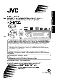 JVC KD-BT22
User Manual
JVC KD-BT22
User Manual
-
JVC KD-BT22
Manual
-
 JVC KD-DV6207
Manual
JVC KD-DV6207
Manual
-
 JVC KD-DV7308
Manual
JVC KD-DV7308
Manual