Page 3 - Table of Contents
Table of Contents INTRODUCTION ............................................... 2 Contact Info.................................................... 2Machine Description ...................................... 2Manual Accuracy ........................................... 2Identification ....................
Page 4 - INTRODUCTION; Machine Description; Contact Info; Manual Accuracy
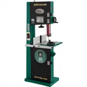
-2- Model G0701 (Mfd. Since 9/17) INTRODUCTION Machine Description The bandsaw is a versatile woodworking tool that is used to perform a wide variety of cuts in wood stock, such as rip cuts, cross cuts, bevel cuts, miter cuts, circular cuts, contour cuts, stacked pattern cuts, etc. The saw blade is ...
Page 5 - Identification
Model G0701 (Mfd. Since 9/17) -3- Identification A. Control Panel B. Guide Post Elevation Control C. Blade Tension Scale D. Lifting Eye Bolts E. Blade Tracking Window F. Upper Wheel Cover Lock Knob G. Guide Post Lock Knob H. Upper Blade Guide Assembly I. Fence w/Resaw Attachment J. Miter Gauge K. Ta...
Page 6 - Components; Front Controls
-4- Model G0701 (Mfd. Since 9/17) Controls & Components To reduce your risk of serious injury, read this entire manual BEFORE using machine. Refer to the following figures and descriptions to become familiar with the basic controls and com-ponents of this machine. Understanding these items and h...
Page 7 - Control Panel
Model G0701 (Mfd. Since 9/17) -5- O. Master Power Key Switch: Turns incoming power ON and OFF. Requires key. P. ON Button: Turns motor ON when pressed. Q. Emergency Stop/Reset Button: Turns motor OFF when pressed. Motor will not start until switch is reset. Twist clockwise to reset. Figure 3. Contro...
Page 8 - Machine Data Sheet
-6- Model G0701 (Mfd. Since 9/17) The information contained herein is deemed accurate as of 4/3/2019 and represents our most recent product specifications. Due to our ongoing improvement efforts, this information may not accurately describe items previously purchased. PAGE 1 OF 3 Model G0701 MACHINE...
Page 10 - NOTICE; Safety Instructions for Machinery
-8- Model G0701 (Mfd. Since 9/17) ELECTRICAL EQUIPMENT INJURY RISKS. You can be shocked, burned, or killed by touching live electrical components or improperly grounded machinery. To reduce this risk, only allow qualified service personnel to do electrical installation or repair work, and always dis...
Page 12 - Additional Safety for Bandsaws
-10- Model G0701 (Mfd. Since 9/17) Additional Safety for Bandsaws Serious cuts, amputation, or death can occur from contact with the moving saw blade during operation or if blade breakage occurs. To reduce this risk, anyone operating this machine MUST completely heed the hazards and warnings below. ...
Page 13 - SECTION 2: POWER SUPPLY; Availability
Model G0701 (Mfd. Since 9/17) -11- SECTION 2: POWER SUPPLY Availability Before installing the machine, consider the avail-ability and proximity of the required power supply circuit. If an existing circuit does not meet the requirements for this machine, a new circuit must be installed. To minimize t...
Page 15 - Unpacking; Needed for Setup
Model G0701 (Mfd. Since 9/17) -13- SECTION 3: SETUP The Model G0701 is a heavy machine. Serious personal injury may occur if safe moving methods are not used. To be safe, get assistance and use power equipment to move the shipping crate and remove the machine from the crate. If you are not experienc...
Page 17 - Site Considerations; Weight Load; Space Allocation
Model G0701 (Mfd. Since 9/17) -15- Site Considerations Figure 6. Minimum working clearances. = Power Connection 33" 37" Weight Load Refer to the Machine Data Sheet for the weight of your machine. Make sure that the surface upon which the machine is placed will bear the weight of the machine,...
Page 18 - Bandsaw; Using Lifting Eye Bolts; Using Wood Blocks
-16- Model G0701 (Mfd. Since 9/17) Moving & Placing Bandsaw Take special care when lifting and moving the Model G0701. Use only one of the following methods to place your bandsaw in its operating location. Using Lifting Eye Bolts 1. With the help of another person to steady the load, use the for...
Page 19 - Anchoring to Concrete Floors; Anchoring to Floor
Model G0701 (Mfd. Since 9/17) -17- Lag shield anchors with lag screws (see below) are a popular way to anchor machinery to a con-crete floor, because the anchors sit flush with the floor surface, making it easy to unbolt and move the machine later, if needed. However, anytime local codes apply, you ...
Page 20 - Dust Collection
-18- Model G0701 (Mfd. Since 9/17) 3. Slide the 8mm flat washer onto the resaw fence lock lever, then insert the assembly through the standard fence (see Figure 11). 4. Thread the T-bar onto the lock lever a couple of turns, align the resaw fence slot and the T-bar, then slide the resaw fence fully ...
Page 21 - Initial Blade Tracking; Adjustment Overview
Model G0701 (Mfd. Since 9/17) -19- Initial Blade Tracking Serious personal injury may occur if the machine accidentally starts dur- ing this procedure. Disconnect the machine from power and keep your hands away from the blade when adjusting blade tracking. Blade tracking is affected by the tilt of t...
Page 24 - Test Run; OFF Button
-22- Model G0701 (Mfd. Since 9/17) Test Run The test run consists of verifying the following: 1. The motor powers up and runs correctly. 2. The stop button and key switch safety fea- tures work correctly. 3. The guide post elevation motor powers up and runs correctly. 4. The foot brake operates corr...
Page 26 - Tensioning Blade; Flutter Method
-24- Model G0701 (Mfd. Since 9/17) Tensioning Blade 4. Move the blade tension quick release lever all the way to the right (as viewed from the rear of the machine) to apply tension, then rotate the tension handwheel until the mark on the blade tension scale matches the one for the blade width (see F...
Page 27 - Deflection Method; Aligning Blade; Upper Blade Bearings
Model G0701 (Mfd. Since 9/17) -25- The deflection method is much more subjective than the flutter method. Each blade will deflect differently and every user will determine what "moderate pressure" means. The following are general guidelines for tensioning the blade with this method. To tensi...
Page 29 - Lower Blade Bearing
Model G0701 (Mfd. Since 9/17) -27- Figure 29. Lower support bearing controls. Support Bearing Shaft Adjustment Bolt Support Bearing Figure 30. Front lower blade guide controls. Rotation Adjustment Bolt Knurled Knob 10. Re-tighten the support bearing shaft adjust- ment bolt and the rotation adjustmen...
Page 30 - Upper Blade Guide Bearings
-28- Model G0701 (Mfd. Since 9/17) Adjusting Blade Guide Bearings When properly adjusted to the blade, the upper and lower blade guide bearings provide side-to-side support that keeps the blade straight while cutting. Figure 32. Front upper blade guide controls (blade guard removed for photo clarity...
Page 31 - Lower Blade Guide Bearings; Aligning Table
Model G0701 (Mfd. Since 9/17) -29- Lower Blade Guide Bearings 1. Make sure the blade is properly tensioned ( Page 24) and tracking correctly (Page 19). 2. DISCONNECT MACHINE FROM POWER! 3. Make sure the blade guide and support bear- ings are properly aligned with the blade, as instructed on Page 25....
Page 32 - Aligning Fence
-30- Model G0701 (Mfd. Since 9/17) 4. Use the finely incremented ruler and record the distance between the miter slot and the front and back of the straightedge. — If the distances are the same, no further adjustments are needed. — If there is a difference between the distanc- es from the miter slot...
Page 35 - SECTION 4: OPERATIONS; Operation Overview
Model G0701 (Mfd. Since 9/17) -33- SECTION 4: OPERATIONS Operation Overview The purpose of this overview is to provide the nov-ice machine operator with a basic understanding of how the machine is used during operation, so the machine controls/components discussed later in this manual are easier to ...
Page 36 - Workpiece
-34- Model G0701 (Mfd. Since 9/17) Basic Functions of a Bandsaw A properly adjusted bandsaw can be safer to operate than most other saws and performs many types of cuts with ease and accuracy. It is capable of performing the following types of cuts: Straight Cuts • Miters • Angles • Compound Angles ...
Page 37 - Operating Foot Brake; Table Tilt
Model G0701 (Mfd. Since 9/17) -35- Operating Foot Brake The Model G0701 is equipped with a foot brake (see Figure 42). Use the brake to cut power to the motor and bring the blade to a halt. NOTICE The foot brake will not stop the bandsaw wheels and blade instantly. DO NOT become over confident and r...
Page 39 - Blade Selection; Blade Terminology; Blade Length
Model G0701 (Mfd. Since 9/17) -37- Blade Selection Selecting the right blade for the cutting task requires knowledge about blade characteristics and cutting priorities (i.e. speed, finish, etc.). Blade Terminology A B C D E F G H I Figure 46. Bandsaw blade components. A. Kerf: The amount of material...
Page 40 - Tooth Style; Tooth Set; Tooth Pitch
-38- Model G0701 (Mfd. Since 9/17) • Straight Cutting: Use the largest width blade that you own. Large blades excel at cutting straight lines and are less prone to wander (known as blade lead —refer to Page 58 for more information on blade lead). Tooth Style Figure 48 illustrates the three main blad...
Page 41 - Blade Material
Model G0701 (Mfd. Since 9/17) -39- Bi-metal Blade: A strip of high-speed tool steel is precision welded to a flexible carbon blade, then teeth are ground into the blade to provide good edge-holding qualities for blades taking a lot of abuse (see Figure 51). Carbon Steel Blade Weld High-Speed Steel F...
Page 42 - Blade Selection Chart
-40- Model G0701 (Mfd. Since 9/17) Blade Selection Chart Cutting Operation Blade Width Narrow ( 1 ⁄ 8 " – 1 ⁄ 4 ") Medium ( 3 ⁄ 16 "– 1 ⁄ 2 ") Wide ( 1 ⁄ 2 "– 3 ⁄ 4 ") Resawing R H S C Ripping Thin Stock R H S M Ripping Thick Stock R H S C Ripping Round Stock R H S M R H S M ...
Page 43 - Blade Breakage; Blade Care
Model G0701 (Mfd. Since 9/17) -41- Blade Breakage Many conditions may cause a bandsaw blade to break. Blade breakage is unavoidable in some cases, since it is the natural result of the peculiar stresses that bandsaw blades must endure. Blade breakage is also due to avoidable circum-stances. Avoidabl...
Page 44 - Changing Blade; Removing Blade; Replacing Blade
-42- Model G0701 (Mfd. Since 9/17) Changing Blade Removing Blade 1. DISCONNECT MACHINE FROM POWER! 2. Release the blade tension. 3. Remove the table insert and the table pin. Adjust the upper and lower guide bearings as far away as possible from the blade. 4. Open the both wheel covers, and with glo...
Page 45 - Ripping; Crosscutting
Model G0701 (Mfd. Since 9/17) -43- Ripping is the process of cutting with the grain of the wood stock. For plywood and other processed wood, ripping simply means cutting down the length of the workpiece. For ripping, a wider blade is better. In most ripping applications, a standard raker tooth style...
Page 46 - Resawing
-44- Model G0701 (Mfd. Since 9/17) 4. Support the ends of the board if necessary. 5. Turn the bandsaw ON. 6. Using push paddles and a push stick, keep pressure against the fence and table, and slowly feed the workpiece into the moving blade until the blade is completely through (see Figure 55). NOTI...
Page 47 - Cutting Curves; Stacked Cuts
Model G0701 (Mfd. Since 9/17) -45- Cutting Curves When cutting curves, simultaneously feed and turn the stock carefully so that the blade follows the layout line without twisting. Use either a nar-rower blade or a blade with more TPI (teeth per inch), or make more relief cuts, to avoid having to bac...
Page 48 - SECTION 5: ACCESSORIES; order online at
-46- Model G0701 (Mfd. Since 9/17) SECTION 5: ACCESSORIES ACCESSORIES Figure 57. D2058A Shop Fox HD Mobile Base. D2058A—Super Heavy-Duty SHOP FOX® Mobile BaseThis patented, super heavy-duty mobile machine base is the strongest mobile base on the market. 18 1 ⁄ 2 " x 24 1 ⁄ 2 " minimum and ad...
Page 49 - Basic Eye Protection
Model G0701 (Mfd. Since 9/17) -47- Figure 62. Recommended products for protect- ing unpainted cast iron/steel on machinery. G5562—SLIPIT ® 1 Qt. Gel G5563—SLIPIT ® 12 Oz. Spray G2871—Boeshield ® T-9 12 Oz. Spray G2870—Boeshield ® T-9 4 Oz. Spray H3788—G96 ® Gun Treatment 12 Oz. Spray H3789—G96 ® Gun...
Page 50 - SECTION 6: MAINTENANCE; Wheel Brushes
-48- Model G0701 (Mfd. Since 9/17) SECTION 6: MAINTENANCE The bandsaw is equipped with two lower brush-es. The brushes should be checked daily and cleaned when they become dirty. There are adjustment brackets that allow the brushes to be adjusted for bristle wear. Refer to Adjusting Wheel and Blade ...
Page 54 - Troubleshooting
-52- Model G0701 (Mfd. Since 9/17) SECTION 7: SERVICE Troubleshooting Symptom Possible Cause Possible Solution Machine does not start or a breaker trips. 1. Emergency OFF button engaged/at fault.2. Key switch turned to "0" position.3. Upper wheel cover safety switch disengaged/at fault. 4. B...
Page 55 - Operations
Model G0701 (Mfd. Since 9/17) -53- Symptom Possible Cause Possible Solution Machine has excessive vibration or noise. 1. V-belt tension incorrect.2. Bent, dull, or damaged blade.3. Loose blade.4. Blade weld contacting support bearing or blade guides. 5. Loose machine component.6. Machine incorrectly...
Page 60 - Blade Lead; Correcting Blade Lead
-58- Model G0701 (Mfd. Since 9/17) Blade Lead Bandsaw blades may wander off the cut line when sawing, as shown in Figure 70. This is called blade lead. Blade lead is usually caused by too fast of a feed rate, a dull or abused blade, or improper tension. If your blade is sharp/undam-aged and you stil...
Page 62 - Checking/Adjusting Guide Post
-60- Model G0701 (Mfd. Since 9/17) Adjusting Guide Post Travel The guide post assembly should remain paral-lel with the blade front-to-back and side-to-side along its length of travel. If it does not, follow these instructions to correctly adjust the guide post. Tools Needed:Machinist's Square ........
Page 65 - Replacing Brake
Model G0701 (Mfd. Since 9/17) -63- 6. Mount the new motor to the gearbox with the screws you removed in Step 3, then connect the new guide post motor wires to the wires inside the frame. 7. Replace the upper wheel. 8. Re-install the upper blade guard. 9. Re-install, tension, and track the blade. Rep...
Page 66 - Aligning Wheels; Checking Coplanarity
-64- Model G0701 (Mfd. Since 9/17) Aligning Wheels Coplanarity Gauge Gauge Positions Tracking Knob Adjustment Hub Wheels Figure 82. Checking for coplanarity. Figure 81. Dimensions of coplanarity gauge. Side View 70" 3-1/2" 19" 19" 32" 1-1/2" Wheel alignment is one of the most...
Page 67 - Shimming Upper Wheel
Model G0701 (Mfd. Since 9/17) -65- — If the wheels are coplanar (Figure 83, A), the straightedge will evenly touch the top and bottom of both wheels. — If the wheels are not coplanar (Figure 83, B), place the straightedge on the lower wheel first (ensuring that it touches both the top and bottom rim...
Page 68 - Adjusting Lower Wheel
-66- Model G0701 (Mfd. Since 9/17) Adjusting Lower Wheel Only do this procedure if you cannot make the wheels coplanar with the tracking knob or by shimming the upper wheel. Make sure the upper wheel is adjusted as close as possible to being coplanar with the lower wheel before beginning. Do this pr...
Page 69 - Wiring Safety Instructions
Model G0701 (Mfd. Since 9/17) -67- SHOCK HAZARD. Working on wiring that is con-nected to a power source is extremely dangerous. Touching electrified parts will result in personal injury including but not limited to severe burns, electrocution, or death. Disconnect the power from the machine before s...
Page 70 - Electrical Overview
-68- Model G0701 (Mfd. Since 9/17) READ ELECTRICAL SAFETY ON PAGE 67! Electrical Overview Rear View A B C Front View D E F G H 230 VAC 1-PH A B C D E F G H Description Wiring Diagram Page Reference A Power Junction Box 69 B Magnetic Switch 69 C Motor Junction Box 69 D Control Panel 70 E Guide Post E...
Page 72 - Control Panel & Guide Post Control
-70- Model G0701 (Mfd. Since 9/17) READ ELECTRICAL SAFETY ON PAGE 67! Control Panel & Guide Post Control wiring diagrams 2 Figure 87. Control panel wiring. Figure 88. Guide post elevation control wiring. Control Panel 22 14 21 13 Key Switch 22 14 21 13 22 14 21 13 ON STOP Switch Down Lamp Up Lam...
Page 74 - Frame
-72- Model G0701 (Mfd. Since 9/17) BUY PARTS ONLINE AT GRIZZLY.COM ! Scan QR code to visit our Parts Store. 1 2 3 4 5 6 7 8 9 10 11 12 13 14 15 16 17 18 19 20 21 22 23 24 25 26 27 28 29 30 31 32 33 34 35 24 3 38 39 40 51 52V2 52V2-2 52V2-1 52V2-3 53 54 55 56 74 75 76 77 78 75 91 92 93 94 3 3 22 27 2...
Page 75 - Frame Parts List
Model G0701 (Mfd. Since 9/17) -73- BUY PARTS ONLINE AT GRIZZLY.COM ! Scan QR code to visit our Parts Store. Frame Parts List REF PART # DESCRIPTION REF PART # DESCRIPTION 1 P0701001 TAP SCREW M4 X 8 45V2-1 P0701045V2-1 MOTOR FAN COVER 2 P0701002 TENSION SCALE PLATE 45V2-2 P0701045V2-2 MOTOR FAN 3 P0...
Page 77 - Wheels
Model G0701 (Mfd. Since 9/17) -75- BUY PARTS ONLINE AT GRIZZLY.COM ! Scan QR code to visit our Parts Store. Wheels 100 101 102 103 104 105 106 107 108 109 110 111 112 113 114 116 117 118 119 103 110 104 115 111 110 108 109 110 112 113 114 127A 129 130 131 132 117 118 119 120 124 120 119 117 118 119 ...
Page 78 - Wheels Parts List
-76- Model G0701 (Mfd. Since 9/17) BUY PARTS ONLINE AT GRIZZLY.COM ! Scan QR code to visit our Parts Store. Wheels Parts List REF PART # DESCRIPTION REF PART # DESCRIPTION 100 P0701100 DOOR SAFETY SWITCH CORD 126 P0701126 CAP SCREW M8-1.25 X 20 101 P0701101 DOOR SAFETY SWITCH 127A P0701127A UPPER WH...
Page 79 - Table
Model G0701 (Mfd. Since 9/17) -77- BUY PARTS ONLINE AT GRIZZLY.COM ! Scan QR code to visit our Parts Store. 200 201 202 203 204 205 206 207 208 209 210 211 212 213 214 215 216 217 233 234 235 236 237 238 239 240 241 242 244 245 246 247 248 249 250 Fence Assemblies & Table Miter Gauge Table Base ...
Page 80 - Guides
-78- Model G0701 (Mfd. Since 9/17) BUY PARTS ONLINE AT GRIZZLY.COM ! Scan QR code to visit our Parts Store. Guides Table Tilt Mechanism Blade Guard Upper Blade Guides Lower Blade Guide Assembly 311 312 313 314 315 316 317 318 319 320 321 322 323 324 325 326 327 328 329 330 331 332 333 334 335 336 33...
Page 81 - Guides Parts List
Model G0701 (Mfd. Since 9/17) -79- BUY PARTS ONLINE AT GRIZZLY.COM ! Scan QR code to visit our Parts Store. Guides Parts List REF PART # DESCRIPTION REF PART # DESCRIPTION 300 P0701300 HEX BOLT M8-1.25 X 55 335 P0701335 CAP SCREW M6-1 X 40 301 P0701301 FLAT WASHER 8MM 336 P0701336 LOCK WASHER 6MM 30...
Page 82 - Guide Post Elevation Assembly
-80- Model G0701 (Mfd. Since 9/17) BUY PARTS ONLINE AT GRIZZLY.COM ! Scan QR code to visit our Parts Store. Guide Post Elevation Assembly 400 401 402 403 404 405 406 407 408 409 410 411 412 413 414 415 416 417 418 419 420 421 422 423 424 425 426 427 428 429 guide post elevation assy REF PART # DESCR...
Page 83 - Fence Assembly & Tools
Model G0701 (Mfd. Since 9/17) -81- BUY PARTS ONLINE AT GRIZZLY.COM ! Scan QR code to visit our Parts Store. Fence Assembly & Tools 500 501 502 503 504 505 506 507 508 509 510 511 512 513 514 515 516 517 518 519 520 REF PART # DESCRIPTION REF PART # DESCRIPTION 500 P0701500 LOCK LEVER M8-1.25 X 4...


 Grizzly Industrial G0513A40
User Manual
Grizzly Industrial G0513A40
User Manual
 Grizzly Industrial G0513X2
User Manual
Grizzly Industrial G0513X2
User Manual
 Grizzly Industrial G0513X2BF
User Manual
Grizzly Industrial G0513X2BF
User Manual
 Grizzly Industrial G0514X
User Manual
Grizzly Industrial G0514X
User Manual
 Grizzly Industrial G0514X2B
User Manual
Grizzly Industrial G0514X2B
User Manual
 Grizzly Industrial G0531B
User Manual
Grizzly Industrial G0531B
User Manual
 Grizzly Industrial G0555
User Manual
Grizzly Industrial G0555
User Manual
 Grizzly Industrial G0555LX
User Manual
Grizzly Industrial G0555LX
User Manual
 Grizzly Industrial G0561
User Manual
Grizzly Industrial G0561
User Manual
 Grizzly Industrial G0568
User Manual
Grizzly Industrial G0568
User Manual
 Grizzly Industrial G0613
User Manual
Grizzly Industrial G0613
User Manual
 Grizzly Industrial G0636X
User Manual
Grizzly Industrial G0636X
User Manual
 Grizzly Industrial G0640X
User Manual
Grizzly Industrial G0640X
User Manual
 Grizzly Industrial G0803Z
User Manual
Grizzly Industrial G0803Z
User Manual
 Grizzly Industrial G0807
User Manual
Grizzly Industrial G0807
User Manual