Page 2 - Wiring Diagram
-2- READ ELECTRICAL SAFETY ON PAGE 53 OF OWNER'S MANUAL! Model G0634X (Mfd. Since 04/23) (Replaces Page 54 in Owner's Manual) A B AMP RESET 96 98 1/2 T1/2 T3/6 NO14 ON 3/4 T2/4 L1/1 L3/5 NO13 L2/3 5/6 95 18 22 26 RESET NC21 SDE NC22 Ground Ground Hot 14 13 12 11 G X Y Hot NC NO 3 4 2 1 MA-18 AUSPICI...
Page 3 - Electrical Component Photos
-3- READ ELECTRICAL SAFETY ON PAGE 53 OF OWNER'S MANUAL! Model G0634X (Mfd. Since 04/23) (Replaces Page 55 in Owner's Manual) Electrical Component Photos Figure 79. Magnetic switch. Figure 81. Start capacitor. Figure 82. Run capacitor. Figure 83. Jointer table limit switch. Figure 80. Emergency Stop...
Page 7 - Table of Contents
Table of Contents INTRODUCTION ............................................... 2 Contact Info ................................................... 2 Manual Accuracy ........................................... 2 Main Identification .......................................... 3 Controls & Components...
Page 8 - Contact Info; Manual Accuracy; INTRODUCTION
-2- Model G0634X (Mfd. Since 11/20) We stand behind our machines! If you have ques-tions or need help, contact us with the information below. Before contacting, make sure you get the serial number and manufacture date from the machine ID label. This will help us help you faster. Grizzly Technical Su...
Page 9 - Main Identification
Model G0634X (Mfd. Since 11/20) -3- Main Identification Become familiar with the names and locations of the controls and features shown below to better understand the instructions in this manual. Planer Table Height Lock Lever Planer Table Height Handwheel Emergency Stop Button Magnetic Switch Table...
Page 10 - Components; Jointer Table Adjustment Controls; Power Controls
-4- Model G0634X (Mfd. Since 11/20) Controls & Components To reduce your risk of serious injury, read this entire manual BEFORE using machine. Refer to the following figures and descriptions to become familiar with the basic controls and com- ponents of this machine. Understanding these items an...
Page 12 - Planer Controls
-6- Model G0634X (Mfd. Since 11/20) Planer Controls Q. Thickness Scale: Indicates thickness of finished workpiece. R. Table Height Handwheel: Rotates to raise and lower planer table. S. Table Height Lock Lever: Tightens to secure planer table height adjustment; loosens to allow adjustment. Figure 10...
Page 15 - NOTICE; Safety Instructions for Machinery
Model G0634X (Mfd. Since 11/20) -9- ELECTRICAL EQUIPMENT INJURY RISKS. You can be shocked, burned, or killed by touching live electrical components or improperly grounded machinery. To reduce this risk, only allow qualified service personnel to do electrical installation or repair work, and always d...
Page 17 - Additional Safety for Jointers
Model G0634X (Mfd. Since 11/20) -11- Additional Safety for Jointers KICKBACK. Occurs when workpiece is ejected from machine at a high rate of speed. Kickback injuries occur from getting struck by workpiece or hands being pulled into cutterhead. To reduce the risk of kickback, only use proper workpie...
Page 18 - Additional Safety for Planers
-12- Model G0634X (Mfd. Since 11/20) Additional Safety for Planers Amputation, serious cuts, entanglement, or death can occur from contact with rotating cutterhead or other moving parts! Flying chips can cause eye injuries or blindness. Workpieces or knives thrown by cutterhead can strike nearby ope...
Page 19 - SECTION 2: POWER SUPPLY; Availability
Model G0634X (Mfd. Since 11/20) -13- SECTION 2: POWER SUPPLY Availability Before installing the machine, consider the avail-ability and proximity of the required power supply circuit. If an existing circuit does not meet the requirements for this machine, a new circuit must be installed. To minimize...
Page 21 - Needed for Setup; Unpacking
Model G0634X (Mfd. Since 11/20) -15- SECTION 3: SETUP This machine presents serious injury hazards to untrained users. Read through this entire manu- al to become familiar with the controls and opera- tions before starting the machine! Wear safety glasses during the entire setup process! HEAVY LIFT!...
Page 22 - Inventory
-16- Model G0634X (Mfd. Since 11/20) Inventory The following is a list of items shipped with your machine. Before beginning setup, lay these items out and inventory them. If any non-proprietary parts are missing (e.g. a nut or a washer), we will gladly replace them; or for the sake of expediency, re...
Page 23 - Cleanup
Model G0634X (Mfd. Since 11/20) -17- T23692—Orange Power DegreaserA great product for removing the waxy ship-ping grease from the non-painted parts of the machine during clean up. The unpainted surfaces of your machine are coated with a heavy-duty rust preventative that prevents corrosion during shi...
Page 24 - Site Considerations; Weight Load
-18- Model G0634X (Mfd. Since 11/20) Site Considerations Figure 14. Minimum working clearances. Wall Min. 30" for Maintenance = Electrical Connection Jointer Operation 60" 41 1 / 2 " Feed Direction Planer Operation 63" 41 1 / 2 " Feed Direction Dust Port Weight Load Refer to the ...
Page 25 - Assembly
Model G0634X (Mfd. Since 11/20) -19- Lifting & Placing HEAVY LIFT! Straining or crushing injury may occur from improperly lifting machine or some of its parts. To reduce this risk, get help from other people and use a forklift (or other lifting equipment) rated for weight of this machine. Unbolt...
Page 26 - Dust Collection
-20- Model G0634X (Mfd. Since 11/20) To assemble machine: 1. Remove shaft lock knob and insert cutterhead guard shaft into bracket hole, as shown in Figure 18 . 2. Move fence forward until it touches cutterhead guard. 3. Thread lock knob into bracket so threads fit into shaft groove (see Figure 18),...
Page 27 - Test Run; Connecting Plug to Power Cord; Power Connection
Model G0634X (Mfd. Since 11/20) -21- 2. Tug hose to make sure it does not come off. Note: A tight fit is necessary for proper performance. Figure 20. Example of dust hose attached to planer dust port. Test Run Once assembly is complete, test run the machine to ensure it is properly connected to powe...
Page 28 - Emergency Stop Button; Recommended
-22- Model G0634X (Mfd. Since 11/20) Emergency Stop Button TWIST Figure 21. Resetting the switch. 5. Twist Emergency Stop button clockwise until it springs out (see Figure 21). This resets switch so machine can start. For your convenience, the adjustments listed below have been performed at the fact...
Page 29 - SECTION 4: OPERATIONS; Operation Overview; Typical Jointing Operation
Model G0634X (Mfd. Since 11/20) -23- SECTION 4: OPERATIONS Operation Overview The purpose of this overview is to provide the nov-ice machine operator with a basic understanding of how the machine is used during operation, so the machine controls/components discussed later in this manual are easier t...
Page 30 - Typical Planing Operation
-24- Model G0634X (Mfd. Since 11/20) 1. Operator examines workpiece to make sure it is safe and suitable for planing. — If workpiece is bowed, operator surface planes workpiece on jointer until one side is flat. Doing so ensures that it sits solidly on planer table during operation. 2. Ensures machi...
Page 31 - Requirements; CORRECT
Model G0634X (Mfd. Since 11/20) -25- With Grain Against Grain CORRECT INCORRECT Figure 23 . Correct and incorrect grain alignment to cutterhead (planer). • Minor Cupping: Workpieces with slight cup- ping can be safely supported if cupped side is facing table. On the contrary, workpiece supported on ...
Page 32 - Wood Types
-26- Model G0634X (Mfd. Since 11/20) Figure 24. Minimum dimensions for edge jointing and surface planing (jointer). 1 ⁄ 4 " Min. 3 ⁄ 4 " Min. 12" Min. 12" Min. 1 ⁄ 2 " Min. 1" Min. Jointer-Specific Rules: • Always joint with cupped side of workpiece facing down, otherwise wor...
Page 33 - Setting Jointer; Adjusting Infeed Table Height
Model G0634X (Mfd. Since 11/20) -27- Jointer Depth-of-Cut Scale The depth of cut can be referenced directly from the depth scale located on the front of the jointer, as shown. Note: The depth scale can be calibrated or "zeroed" if it is not correct. Refer to Calibrating Depth Scale for more ...
Page 36 - Edge Jointing
-30- Model G0634X (Mfd. Since 11/20) Edge Jointing To edge joint on jointer: 1. Inspect stock to ensure it is safe and suitable for the operation (see Stock Inspection & Requirements section). 2. Surface plane workpiece (see Surface Planing section). 3. Set infeed table height to desired cutting...
Page 38 - Conversion; Converting for Planer Operations
-32- Model G0634X (Mfd. Since 11/20) Jointer/Planer Conversion 3. Remove dust hose from jointer dust port. 4. Rotate infeed table lock lever (see Figure 33) clockwise, pull it out, and pivot table upward. Figure 33 . Location of infeed table lock lever. 5. Raise outfeed table in same manner as you d...
Page 39 - Planing Tips; Converting for Jointer Operations
Model G0634X (Mfd. Since 11/20) -33- Planing Tips • Inspect your lumber for twisting or cupping, and surface one face on a jointer if necessary before planing workpiece. • Scrape off all glue when planing glued-up panels. Dried glue can quickly dull knives/inserts. • DO NOT plane more than one piece...
Page 40 - Chipped Grain; Chip Marks or Indentations; Rippled Cut
-34- Model G0634X (Mfd. Since 11/20) Common Planing Problems Below is a list of wood characteristics you may encounter when planing. The following descrip-tions of defects will give you some possible answers to problems you may encounter while planing different materials. Possible solutions fol-low ...
Page 42 - SECTION 5: ACCESSORIES; order online at
-36- Model G0634X (Mfd. Since 11/20) SECTION 5: ACCESSORIES Installing unapproved accessories may cause machine to malfunction, resulting in serious personal injury or machine damage. To reduce this risk, only install accessories recommended for this machine by Grizzly. NOTICE Refer to our website o...
Page 43 - SECTION 6: MAINTENANCE; Schedule
Model G0634X (Mfd. Since 11/20) -37- SECTION 6: MAINTENANCE To reduce risk of shock or accidental startup, always disconnect machine from power before adjustments, maintenance, or service. Schedule For optimum performance from this machine, this maintenance schedule must be strictly followed. Ongoin...
Page 46 - Troubleshooting
-40- Model G0634X (Mfd. Since 11/20) Review the troubleshooting procedures in this section if a problem develops with your machine. If you need replacement parts or additional help with a procedure, call our Technical Support. Note: Please gather the serial number and manufacture date of your machin...
Page 49 - Adjusting Pulley
Model G0634X (Mfd. Since 11/20) -43- 3. Remove belt tension knob (see Figure 49 on Page 42 ). 4. Loosen (4) motor mount adjustment nuts and raise motor (see Figure 52) to completely remove V-belt tension. It may help to use a 2x4 as lever to lift motor. 5. Remove both belts and replace them with new...
Page 51 - Checking Jointer; Checking Outfeed Table Parallelism
Model G0634X (Mfd. Since 11/20) -45- 4. Try to fit feeler gauge or combination of feeler gauges 0.062" to 0.069" between bottom of ruler and cutterhead body, as shown in Figure 59 . — If feeler gauge slides with slight resistance between ruler and cutterhead and no gaps appear, go to Step 5....
Page 52 - Correcting Outfeed Table Parallelism
-46- Model G0634X (Mfd. Since 11/20) Straightedge Outfeed Table Infeed Table Figure 61. Infeed and outfeed tables set parallel. Black Lines RepresentStraightedge Positionsfrom Overhead View Figure 62. Straightedge positions for checking infeed/outfeed table parallelism. Correcting Outfeed Table Para...
Page 53 - Adjusting Infeed Table Parallelism
Model G0634X (Mfd. Since 11/20) -47- Adjusting Infeed Table Parallelism For safe and proper cutting results, both jointer tables must be parallel to the cutterhead. The correct order for adjusting table parallelism is to first adjust the outfeed table parallel with the cutterhead, then adjust the in...
Page 54 - Table Parallelism Inspection
-48- Model G0634X (Mfd. Since 11/20) Checking Planer Table Parallelism Table Parallelism Inspection The easiest way to check that your planer table is parallel with the headstock is to plane a workpiece and then measure its thickness in multiple loca- tions. Extra care must be taken to ensure accu- ...
Page 55 - Adjusting Table Lock
Model G0634X (Mfd. Since 11/20) -49- Replacing Carbide Inserts Items Needed: Qty T-Handle Wrench w/T-20 Torx Bit ..................... 1 The cutterhead is equipped with 48 indexable car- bide inserts. Each insert can be rotated to reveal any one of its four cutting edges. Therefore, if one cutting e...
Page 56 - Calibrating Depth; Setting 90° Fence Stop
-50- Model G0634X (Mfd. Since 11/20) The depth scale on the infeed table can be cali- brated or "zeroed" if it is not correct. Items Needed Qty Straightedge ...................................................... 1 Phillips Screwdriver ........................................... 1 To calibrat...
Page 57 - Adjusting Gibs
Model G0634X (Mfd. Since 11/20) -51- To adjust table gibs: 1. Using adjustable wrench, loosen infeed table gib nut under rear of table (see Figure 76). 2. Loosen lock nut on 45˚ fence stop screw (see Figure 75 ). Figure 75 . Adjusting fence 45˚ outward. 3. Adjust 45˚ stop screw until fence is exactl...
Page 59 - Wiring Safety Instructions
Model G0634X (Mfd. Since 11/20) -53- SHOCK HAZARD. Working on wiring that is con-nected to a power source is extremely dangerous. Touching electrified parts will result in personal injury including but not limited to severe burns, electrocution, or death. Disconnect the power from the machine before...
Page 62 - Stand
-56- Model G0634X (Mfd. Since 11/20) BUY PARTS ONLINE AT GRIZZLY.COM ! Scan QR code to visit our Parts Store. SECTION 9: PARTS We do our best to stock replacement parts when possible, but we cannot guarantee that all parts shown are available for purchase. Call (800) 523-4777 or visit www.grizzly.co...
Page 63 - Stand Parts List
Model G0634X (Mfd. Since 11/20) -57- BUY PARTS ONLINE AT GRIZZLY.COM ! Scan QR code to visit our Parts Store. Stand Parts List REF PART # DESCRIPTION REF PART # DESCRIPTION 1 P0634X001 FRAME 21 P0634X021 CAP SCREW 3/8-16 X 1 1-1 P0634X001-1 HINGE SHAFT BRACKET RIGHT 21-1 P0634X021-1 CAP SCREW 3/8-16...
Page 64 - Jointer Table
-58- Model G0634X (Mfd. Since 11/20) BUY PARTS ONLINE AT GRIZZLY.COM ! Scan QR code to visit our Parts Store. Jointer Table 102 105 110 101 103 112 106 107 113 108 108 109 109 118 114 120 122 120 121 126 124 117 125 124 117 125 133 109 130 132 131 129 133 109 130 132 131 134 121 121 129 111 113 114 ...
Page 66 - Drive Assembly
-60- Model G0634X (Mfd. Since 11/20) BUY PARTS ONLINE AT GRIZZLY.COM ! Scan QR code to visit our Parts Store. Drive Assembly 301 302 313 314 319 341 308 306 304 312 309 305 303 309 320 322 322 315 321 316 324 340 311 310 338 329 327 326 335 325 337 331 332 317 328 334 307 333 323 336 330 336 330 329...
Page 67 - Planer Table
Model G0634X (Mfd. Since 11/20) -61- BUY PARTS ONLINE AT GRIZZLY.COM ! Scan QR code to visit our Parts Store. Planer Table 404 405 411 402 403 409 407 401 406 415 408-1 419 410 417 418 420 421 422 423 424 425 414 421 412 413 437 438 427 428 429 430 434 421 433 426 436 431 432 414 420 435434 408-2 40...
Page 68 - Limit Switch
-62- Model G0634X (Mfd. Since 11/20) BUY PARTS ONLINE AT GRIZZLY.COM ! Scan QR code to visit our Parts Store. Limit Switch 501-2 504 502 506 501-1 501-3 503 505 509 511 510 511 507 512 507 507 513 514 515 508 508 517 508 507 REF PART # DESCRIPTION REF PART # DESCRIPTION 501-1 P0634X501-1 SWING LEVER...
Page 69 - Fence
Model G0634X (Mfd. Since 11/20) -63- BUY PARTS ONLINE AT GRIZZLY.COM ! Scan QR code to visit our Parts Store. Fence 602 601 600 603 604 619 625 626 615 612 610 605 605 607 620 618 616 617 627 624 623 621 614 613 612 611 606 621 609 640 641 608 608-1 610-1 610-2 639 607 636 631 636 643 637 635 634 64...


 Grizzly Industrial G0453Z
User Manual
Grizzly Industrial G0453Z
User Manual
 Grizzly Industrial G0505
User Manual
Grizzly Industrial G0505
User Manual
 Grizzly Industrial G0544
User Manual
Grizzly Industrial G0544
User Manual
 Grizzly Industrial G0815
User Manual
Grizzly Industrial G0815
User Manual
 Grizzly Industrial G0890
User Manual
Grizzly Industrial G0890
User Manual
 Grizzly Industrial G0891
User Manual
Grizzly Industrial G0891
User Manual
 Grizzly Industrial G0939
User Manual
Grizzly Industrial G0939
User Manual
 Grizzly Industrial G0940
User Manual
Grizzly Industrial G0940
User Manual
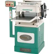 Grizzly Industrial G1021X2
User Manual
Grizzly Industrial G1021X2
User Manual
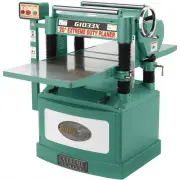 Grizzly Industrial G1033X
User Manual
Grizzly Industrial G1033X
User Manual
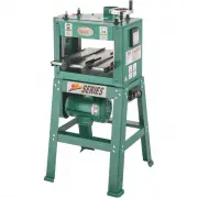 Grizzly Industrial G1037Z
User Manual
Grizzly Industrial G1037Z
User Manual
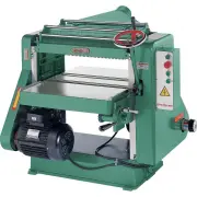 Grizzly Industrial G5851Z
User Manual
Grizzly Industrial G5851Z
User Manual
 Grizzly Industrial G9961
User Manual
Grizzly Industrial G9961
User Manual