Page 2 - Specifications; Warnings; Warning Symbol; WARNING; Caution Symbol; CAUTION
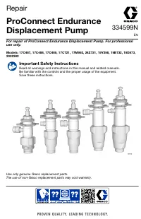
2 309662 Specifications This equipment is not intended for use with flammable or combustible materials used in places such as cabinet shops or other “factory” or fixed locations. If you intend to use this equipment in this type of application, you must comply with NFPA 33 and OSHA requirements for t...
Page 3 - FIRE AND EXPLOSION HAZARD; PRESSURIZED ALUMINUM PARTS HAZARD
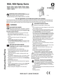
309662 3 The following are general Warnings related to the safe setup, use, maintenance and repair of this equipment. Additional, more specific warnings may be found throughout the text of this manual where applicable. WARNING FIRE AND EXPLOSION HAZARD Flammable fumes, such as solvent and paint fume...
Page 4 - EQUIPMENT MISUSE HAZARD; TOXIC FLUID HAZARD
4 309662 WARNING INSTRUCTIONS EQUIPMENT MISUSE HAZARD Misuse can cause death or serious injury. D Read all instruction manuals, tags, and labels before operating the equipment. D Use equipment only for its intended purpose. Call your Graco distributor for information. D Do not exceed the maximum wor...
Page 5 - Component Description; Flow and Air Control; TexSpray Hoses
309662 5 Component Description Flow and Air Control Fig. 1. The flow control (A) has a shut off and pressure relief feature to soft start each time the gun is trig- gered, instead of a blast of unatomized material. The flow control has three modes: D LOW/MED/HIGH: Triggering the gun sends an air sig...
Page 6 - Compressor Requirements; Maintenance; D E
6 309662 Component Description Compressor Requirements NOTE: This sprayer requires an external air compres- sor. CAUTION Install an air filter on external air compressor to reduce contamination to spray system. Air compressor range: 10 scfm to 35 scfm, 30 to 140 psi (0.2--0.97 MPa, 2 to 9.7 bar) Mat...
Page 7 - Troubleshooting
309662 7 Troubleshooting To reduce risk of injury due to sprayer starting unexpectedly, shut off engine before performing checks or service. WARNING Check everything in chart before disassembling sprayer. PROBLEM CAUSE SOLUTION Engine does not start Engine switch not ON Turn engine switch ON Out of ...
Page 10 - Displacement Pump Repair; Removal; Repair
10 309662 Displacement Pump Repair Removal To reduce risk of injury due to sprayer starting unexpectedly, shut off engine before performing checks or service. WARNING 1. Fig. 4. Flush sprayer. Remove suction hose elbow (150a), pump outlet hose (A) and drain hose (64). TI3021B Fig. 4 27 63 22 3 150a ...
Page 11 - Installation
309662 11 Displacement Pump Repair Installation 1. Fig. 4. Screw assembled dump valve manifold (85) and air cylinder (22) into pump (3). 2. Fig. 5. Pull piston rod (201) out of pump (3) 2 to 3 inches (50 to 75 mm). WARNING MOVING PARTS HAZARD If pin works loose, parts could break off due to force of...
Page 12 - Pump Repair; Disassemble Pump; Clean and Inspect All Parts
12 309662 Pump Repair To reduce risk of injury due to sprayer starting unexpectedly, shut off engine before performing checks or service. WARNING Disassemble Pump 1. See Displacement Pump Repair on page 10 to remove pump. 2. Use a hammer on tabs of lug nut (214) to loosen foot valve housing. 3. Fig....
Page 14 - Bearing Housing & Connecting Rod
14 309662 Bearing Housing & Connecting Rod Removal To reduce risk of injury due to sprayer starting unexpectedly, shut off engine before performing checks or service. WARNING 1. Fig. 8. Perform steps 1--8 of Displacement Pump, Removal , page 10. 2. Remove four screws (40) and front cover (21). 3...
Page 15 - Drive Housing
309662 15 Drive Housing TI3023A Torque to25 ft-- lb(34 N.m) Fig. 9 1 19 39 8 8g 8h 91 36 58 40 150a 64 1 A Apply remaininggrease to theseareas 2 2 59 84 92 84 36 93 56 21 To reduce risk of injury due to sprayer starting unexpectedly, shut off engine before performing checks or service. WARNING 1. Fi...
Page 17 - Collar
309662 17 Pinion Assembly/Rotor/Field/Shaft/Clutch Installation 1. Fig. 14. Lay two stacks of two dimes on smooth bench surface. 2. Lay armature (89) on two stacks of dimes. 3. Press center of clutch down on bench surface. Fig. 14 4a 8705A 0.12 ± .01 in. (3.0 ± .25 mm) 4. Install armature (89) on en...
Page 18 - Clutch Housing
18 309662 Clutch Housing Removal 1. Fig. 16. Remove four capscrews (42) and lock- washers (29) which hold clutch housing (88) to engine. 2. Remove screw (101) from under mounting plate (D). 3. Remove engine key (90). 4. Pull off clutch housing (88). Installation 1. Fig. 16. Push on clutch housing (8...
Page 19 - Engine; SPRAYER WIRING DIAGRAM; X Black
309662 19 Engine Removal 1. Remove Pinion Assembly/Rotor/Field/Pinion/ Clutch, Clamp and Clutch Housing , as in- structed on pages 16, 17, and 18. 2. Fig. 17. Disconnect all necessary wiring. 3. Fig. 18. Remove two locknuts (18) and screws (17) from base of engine. 4. Lift engine carefully and place...
Page 23 - Parts - Dump Manifold
309662 23 Parts - Dump Manifold See page 21 for parts description and page 20 for location on sprayer. 23 n 22 n 68 n 30 79 n 47 n 63a 45 n 41 n 82 n 96 n 85 n 31 1 Prime Valve Repair Kit 234231 Installation1. Replace all parts shown for (47).2. Apply blue LockTite to threads of screw (68).3. Detail...
Page 24 - Parts - Displacement Pump
24 309662 Parts - Displacement Pump Model 235166, Series A Includes items 201227 RefNo. Part No. Description Qty 201 188437 PISTON ROD 1 202 187068 PACKING NUT 1 203 188560* V-PACKING, poly 2 204 187939* GLAND, male 1 205 188557* O-RING 2 206 187934 PISTON HOUSING 1 207 188559* O-RING, fluoroelastom...
Page 25 - Parts - Pinion and Drive Housing Repair Kits
309662 25 Parts - Pinion and Drive Housing Repair Kits Ref No. 58 and 8 Pinion Housing Repair Kit Ref No. 8: Drive Housing Repair Kit RefNo. Part No. Description Qty RefNo. Part No. Description Qty 58 245399 KIT, repair, pinion housing 1 58b 105489 PIN 2 58d* 241114 PINION SHAFT 1 58e 112770 RETAINI...
Page 26 - Accessories; GENUINE GRACO
26 309662 Accessories USE ONLY GENUINE GRACO PARTS AND ACCESSORIES Air And Material Hose Kit 235737 Max. Working Pressure Fluid: 750 psi (5.18 MPa, 51.7 bar) Air: 300 psi (2.07 MPa, 20.7 bar) 50 ft (15.2 m) hoses to supplement 50 ft (15.2 m) hose kit supplied with sprayer. Use up to three more hose ...
Page 27 - Technical Data; Dimensions
309662 27 Technical Data Honda GX160 Engine Power Rating @ 3600 rpm ANSI 5.5 Horsepower . . . . . . . . . . . . . . . . . . . . . . . . . DIN 6270/DIN 6271 NA 2.9 Kw--4.0 Ps . . . . . . . . . . . . . . . . . . . . . . . . . . . NB 3.6 Kw--4.9 Ps . . . . . . . . . . . . . . . . . . . . . . . . . . . ...
Page 28 - Graco Warranty and Disclaimers
28 309662 Graco Warranty and Disclaimers Graco warrants all equipment referenced in this document which is manufactured by Graco and bearing its name to be free from defects in material and workmanship on the date of sale to the original purchaser for use. With the exception of any special, extended...