Page 2 - LIMITED WARRANTY AND LIMITATION OF LIABILITY
LIMITED WARRANTY AND LIMITATION OF LIABILITY Each Fluke product is warranted to be free from defects in material and workmanship under normal use and service. The warranty period is three years and begins on the date of shipment. Parts, product repairs, and services are warranted for 90 days. This w...
Page 3 - Table of Contents; Title
i Table of Contents Title Page Introduction ............................................................................................... 1 Contact Fluke ............................................................................................ 1 Safety Information .................................
Page 5 - Warning; Unsafe Voltage; OL
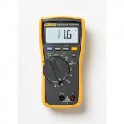
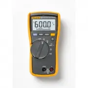
1 Introduction The Fluke Model 116, is a battery-powered, true-rms multimeter (the Meter or Product) with a 6000-count display and a bar graph. Contact Fluke Fluke Corporation operates worldwide. For local contact information, go to our website: www.fluke.com To register your product, view, print, o...
Page 6 - Display; Table 1; Item; VW
116 Users Manual 2 Display Table 1 shows the areas of the display. Table 1. Display Item Symbol Description s The Meter function is set to Continuity. R The Meter function is set to Diode Test O Input is a negative value. Z X Unsafe voltage. Measured input voltage ≥ 30 V, or voltage overload...
Page 7 - Terminals; Table 2; Table 3; Error Messages
True-rms Multimeter Terminals 3 Terminals Table 2 is a list of terminals on the Meter. Error Messages Table 3 is a list of error messages for the Meter. Table 2. Terminals No. Description Common (return) terminal for all measurements. Input terminal for all measurements. Table 3. Error Messages ...
Page 8 - Rotary Switch Positions; Switch Position
116 Users Manual 4 Rotary Switch Positions Table 4 is a list of the rotary switch positions and features. Battery Saver™ (Sleep Mode) If the Meter is ON, but inactive and not connected to voltage for more than 20 minutes, the display goes blank to save battery life. To use the Meter, press any butto...
Page 9 - MIN MAX AVG Recording Mode; Note; Display HOLD; XW; Backlight
True-rms Multimeter MIN MAX AVG Recording Mode 5 MIN MAX AVG Recording Mode The MIN MAX AVG recording mode captures the minimum and maximum input values (ignoring overloads), and calculates a running average of all readings. When the Meter detects a new high or low, the Meter beeps. Note Autoranging...
Page 10 - Manual and Autoranging; Manual; Button; bEEP
116 Users Manual 6 Manual and Autoranging The Meter has both Manual and Autorange modes. The Meter defaults to Autorange. To toggle between Manual and Autorange, push q for 1 second. • In the Autorange mode, the Meter selects the range with the best resolution.• In the Manual Range mode, you overrid...
Page 11 - Making Basic Measurements; removing the common test lead.; Measuring Resistance
True-rms Multimeter Making Basic Measurements 7 Making Basic Measurements When connecting the test leads to the circuit or device, connect the common ( COM ) test lead before connecting the live lead; when removing the test leads, remove the live lead before removing the common test lead. XW Warning...
Page 12 - Measuring AC and DC Millivolts
116 Users Manual 8 Measuring AC and DC Voltage Using Auto Volts Selection With the function switch in the x position, the Meter automatically selects a dc or ac voltage measurement based on the input applied between the V or + and COM jacks. This function also sets the Meter’s input impedance to app...
Page 13 - Measuring AC or DC Current; To measure flame rectification circuits:
True-rms Multimeter Making Basic Measurements 9 Measuring AC or DC Current XW Warning To avoid personal injury or damage to the Meter:• Never attempt to make an in-circuit current measurement when the open-circuit potential to earth is > 600 V. • Use the proper terminals, switch position, and ran...
Page 14 - Users Manual; Measuring Capacitance
116 Users Manual 10 Measuring Capacitance Measuring Temperature XW Warning To prevent risk of electric shock, do NOT connect 80BK to live circuits. 80BK Type K
Page 15 - Measuring Frequency; Making Low Impedance Capacitance Measurements; LCAP; shows on the display.; Hz
True-rms Multimeter Making Basic Measurements 11 Measuring Frequency XW Warning To prevent electrical shock, disregard the bar graph for frequencies >1 kHz. If the frequency of the measured signal is >1 kHz, the bar graph and Z are unspecified. The Meter measures the frequency of a signal by c...
Page 16 - Testing Diodes
Page 17 - Measuring Current above 600; and a polarity indicator (
True-rms Multimeter Making Basic Measurements 13 Measuring Current above 600 μ A The millivolt and voltage function of the Meter can be used with an optional mV/A output Current Probe to measure currents that exceed the rating of the Meter. Make sure the Meter has the correct function, AC or DC, sel...
Page 18 - Maintenance; Replacing the Battery; See; Figure 1. Disassembly; Install and tighten battery door screw.; Cleaning
116 Users Manual 14 Maintenance Maintenance of the Meter consists of battery replacement and case cleaning. Replacing the Battery XW Warning To prevent shock, injury, or damage to the Meter, remove test leads from the Meter before opening the case or battery door. See Figure 1 for disassembly. Figur...
Page 19 - Specifications
True-rms Multimeter Specifications 15 Specifications Accuracy is specified for 1 year after calibration, at operating temperatures of 18 °C to 28 °C, with relative humidity at 0 % to 90 %.Extended specifications are available at www.fluke.com . Maximum voltage between any terminal and earth ground ....
Page 20 - Table 6. Accuracy Specifications
116 Users Manual 16 Table 6. Accuracy Specifications Function Range Resolution Accuracy ± ([% of Reading] + [Counts]) DC Millivolts 600.0 mV 0.1 mV 0.5 % + 2 DC Volts 6.000 V 0.001 V 0.5 % + 2 60.00 V 0.01 V 600.0 V 0.1 V DC, 45 to 500 Hz 500 Hz to 1 kHz Auto-V LoZ [1] True-rms 600.0 V 0.1 V 2.0 % +...
Page 21 - Table 7. Input Characteristics
True-rms Multimeter Specifications 17 Hz (V or A input) [3] 99.99 Hz 0.01 Hz 0.1 % + 2 999.9 Hz 0.1 Hz 9.999 kHz 0.001 kHz 50.00 kHz 0.01 kHz Notes: [1] All ac ranges except Auto-V LoZ are specified from 1 % to 100 % of range. Auto-V LoZ is specified from 0.0 V. Because inputs below 1 % of range are...