Page 3 - SAFETY AND WARNINGS; SAVE THESE INSTRUCTIONS; IMPORTANT SAFETY INSTRUCTIONS!; Cleaning and servicing
3 1 SAFETY AND WARNINGS IMPORTANT! SAVE THESE INSTRUCTIONS The models shown in this installation guide may not be available in all markets and are subject to change at any time. For current details about model and specification availability in your country, please go to our website fisherpaykel.com ...
Page 4 - THIS APPLIANCE MUST BE INSTALLED BY A QUALIFIED INSTALLER.; PARTS SUPPLIED FOR INSTALLATION
4 IMPORTANT! THIS APPLIANCE MUST BE INSTALLED BY A QUALIFIED INSTALLER. ● Improper installation, adjustment, alteration, services, or maintenance can cause injury or property damage. Consult a qualified installer or the service agent. ● The use of suitable protective clothing/gloves is recommended w...
Page 5 - MODEL IDENTIFICATION; NOTE: Model features may vary; OR90 INDUCTION MODELS; PRIOR TO INSTALLATION; Unpacking and handling
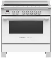
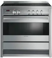
5 4 MODEL IDENTIFICATION OR90SCI1OR90SCI4OR90SCI6OR90SDI6 NOTE: Model features may vary OR90 INDUCTION MODELS 5 PRIOR TO INSTALLATION Unpacking and handling ● Inspect the cooker to verify that there is no shipping damage. If any damage is detected, call the shipper and initiate a damage claim. Fishe...
Page 6 - PRODUCT DIMENSIONS; Optional kickstrip available (purchased separately)
6 6 PRODUCT DIMENSIONS FRONT TOP SIDE E B C C A D F G PRODUCT DIMENSIONS OR90SCI MODELS mm A Overall height of cooker (from floor to top of cooktop, excluding optional backguard) min 898 max 946 B Overall width of cooker 897 C Overall depth of cooker(from front of cooker to rear of island trim/backg...
Page 7 - Note; ISO; CLEARANCE DIMENSIONS; OR90SCI MODELS; Width of cabinetry opening
7 F 7 CLEARANCE DIMENSIONS D C A B B E Electrical (see diagrams following) COOKING SURFACE Note ● The cabinetry surrounding the cooker must be heat resistant and capable of withstanding temperatures of 75°C above room temperature. ● Do not install the cooker near flammable materials such as curtains...
Page 8 - FITTING THE OPTIONAL BACKGUARD; Backguard (supplied with some models only); Remove the screws and spacers on the rear of the cooktop.; LOCATION OF ELECTRICAL SUPPLY; SUPPLY AREA DIMENSIONS; Width of electrical supply areas
8 8 FITTING THE OPTIONAL BACKGUARD Backguard (supplied with some models only) ● Remove the screws and spacers on the rear of the cooktop. ● Assemble the backguard as shown and fix onto the back of the cooker using the same screws and spacers. ● Fix the backguard onto the cooker using the screws prov...
Page 9 - VENTILATION REQUIREMENTS; IMPORTANT; Wall Installation
9 !0 VENTILATION REQUIREMENTS A suitable ventilation hood may be installed above the cooker.Fisher & Paykel has a choice of ventilation hoods designed to match the rest of our kitchen appliance family. See fisherpaykel.com or your local dealer for more details. IMPORTANT ● Consult local building...
Page 10 - Fitting the adjustable feet; Take care not to damage the cooker during this operation.; FITTING THE ADJUSTABLE FEET; Stand cooker back upright.
10 Fitting the adjustable feet The adjustable feet must be fitted to the base of the cooker before use.Rest the rear of the cooker on a piece of the polystyrene packaging exposing the base for the fitting of the feet. IMPORTANT Take care not to damage the cooker during this operation. Fit the four l...
Page 11 - MOVING THE COOKER
11 IMPORTANT! ● When raising cooker to upright position always ensure two people carry out this manoeuvre to prevent damage to the adjustable feet. ● Be careful: do not lift the cooker by the oven door handle, the hob rail or by lifting the cooktop trim as this may damage the appliance. ● When movin...
Page 12 - INSTALLING THE ANTI-TIP BRACKET; To fit the anti-tip bracket; Slide the cooker into place and adjust the height of the bracket so
12 !3 INSTALLING THE ANTI-TIP BRACKET To fit the anti-tip bracket 1 Loosely fix the anti-tip bracket to the wall using the supplied screws. ● Drill two 8mm diameter holes in the wall and insert the supplied plastic sleeve anchors before inserting the screws. 2 Slide the cooker into place and adjust ...
Page 13 - To remove the storage/warming drawer; Be sure storage/warming drawer is empty before removing.
13 6 Fit the lock pin through the bracket as shown 7 Insert the drawer guides onto the sliding runners on either side of the cooker interior. ● Make sure they are correctly lined up on both sides of the drawer. 8 Gently close the drawer completely. The safety catches will automatically lock into pla...
Page 14 - ELECTRICAL CONNECTION; The switch must always be accessible.; MODEL CODE; This cooker must be earthed.
14 !4 ELECTRICAL CONNECTION ● If the installation requires alterations to the domestic electrical system, call a qualified electrician. The electrician should also check that the electrical system is suitable for the electricity drawn by the cooker. ● The appliance must be connected to the mains ele...
Page 15 - ELECTRICAL FEEDER CABLE CONNECTION; PE; Feeder cable section; Remove the screws that hold the cover in place at the
15 !5 ELECTRICAL FEEDER CABLE CONNECTION IMPORTANT! The power supply cable must be connected by an authorised service person PE N L 220-240 V AC IMPORTANT! Do not to unscrew the strain relief from the cooker Feeder cable section Use a type of cable according to the applicable local regulations.220-2...
Page 16 - FINAL CHECKLIST; Complete and keep for safe reference:; OPERATION
16 TO BE COMPLETED BY THE INSTALLER GENERAL F Placement of unit. F Specified clearance maintained to cabinet surfaces. F Unit Level – front to back, side to side. F All packaging material and tie straps removed. F Island trim or optional backguard correctly attached. F The anti-tip bracket is correc...