Page 2 - содержание
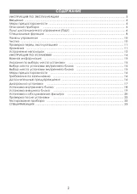
ИНСТРУКЦИЯ ПО ЭКСПЛУАТАЦИИ ………………………………………………………… 3 Введение ………………………………………………………………………………………… 4 Меры предосторожности …………………………………………………………………… 4 Описание прибора ………………………………………………………………………… 5 Пульт дистанционного управления (ПДУ) ……………………………………………… 6 Специальные функции ………………………………………………………………...
Page 3 - инструкция по эксплуатации
Page 4 - дополнительные положения; ВВедение
4 УВАЖАЕМЫЙ ПОКУПАТЕЛЬ! Мы поздравляем Вас с удачным выбором! Вы стали обладателем продукции марки ELENBERG, которая отличается про - грессивным дизайном и хорошим качеством исполнения. Мы надеемся, что наша продукция станет Вашим спутником на долгие годы. Чтобы максимально полно и безопасно использ...
Page 5 - описание прибора
5 Система защиты от замерзания Когда кондиционер работает в режиме охлаждения при низкой температу - ре окружающей среды, возможно образование льда на элементах тепло - обмена. Если температура теплообменника внутреннего блока опускается неже 0 ºС, кондиционер автоматически выключается. 1. Шнур пита...
Page 6 - описание кнопок пду
6 описание кнопок пду • Для нормальной передачи сигнала между ПДУ и прибо - ром не должно быть препятствий; • Будьте осторожны - пульт чувствителен к внешнему меха - ническому воздействию; • Не допускайте попадания воды на ПДУ. • Не оставляйте ПДУ возле источников тепла или под прямы - ми солнечными...
Page 8 - специальные Функции
8 основные операции 1. Нажмите кнопку ON/OFF, чтобы включить/выключить прибор. Замечание: При выключении кондиционера жалю - зи автоматически закрываются. 2. Используя кнопку MODE, установите нужный Вам режим. 3. Установите наиболее комфортную температуру с помощью кнопок +/-. 4. Чтобы установить ск...
Page 10 - Чистка передней панели; панель упраВления
10 Панель управления, расположенная на внутреннем блоке кондиционера включает в себя кнопку “Авто/Стоп” (AUTO/STOP) и переключатель режимов. Функции кнопки “Авто/Стоп” (AUTO/STOP): • Нажмите эту кнопку, когда кондиционер выклю - чен, чтобы включить автоматический режим ра - боты. В этом режиме конди...
Page 11 - Чистка воздушного фильтра; проВерка перед эксплуатацией
11 Чистка воздушного фильтра Загрязненный фильтр снижает эффективность ра - боты прибора. Регулярно производите чистку воздуш - ного фильтра. При извлечение воздушного фильтра не прикасайтесь к решетке радиатора. 1. Извлечение фильтра а) Поднимите переднюю панель внутреннего бло - ка. b) Извлеките ф...
Page 12 - устранение неполадок
12 ВНИМАНИЕ: • Любой ремонт прибора должен осуществляться в сервисном центре. • Внимательно прочитайте данный раздел перед тем, как обратиться в сер - висный цент. ПРОБЛЕМА РЕШЕНИЕ Кондиционер не за - пускается сразу после остановки. Защитная система кондиционера не позволяет запускает его ранее, че...
Page 14 - инструкция по устаноВке
Page 17 - диаграММа устаноВки
Page 18 - установка внутреннего блока; устаноВка Внутреннего блока
18 установка тыльной панели 1. Устанавливайте тыльную панель только горизонтально, т.к. сливное соеди - нение находится слева - эта сторона должна быть незначительно ниже. 2. Убедитесь, что все требо - вания к установке выпол - нены и закрепите тыльную панель. 3. Убедитесь, что тыльная па - нель зак...
Page 19 - подключение трубок; подключение проводов; прокачка воздуха и проверка на протекание; устаноВка Внешнего блока
19 1). Удалите заглушку 1, если прокладыва - ете только электропроводку; 2). Удалите заглушки 1 и 2 или 1, 2 и 3, если прокладываете электропроводку и соединительные трубки. 2. Объедините электропроводку и соеди - нительные трубки с помощью изолирую - щей ленты (Рис. 3). 3. Навесьте внутренний блок ...
Page 20 - устаноВка и обслужиВание Фильтра
20 помпы изменился, а показания мультиметра равны 0, затяните крепление соединитель - ного шланга. 5. Подождите 15 минут и убедитесь, что пока - зания мультиметра соответствуют следую - щему значению: -1.0 x 10 5 Па (-76 cmHg). 6. Полностью откройте клапаны высокого и низкого давления. 7. Снимите со...
Page 21 - Чистка и обслуживание
21 3. Установите воздушный фильтр на место и за - кройте переднюю панель (Рис. Г). Чистка и обслуживание Снимайте дополнительный фильтр при чистке воздушного фильтра. Не ис - пользуйте воду для чистки фильтра с ионами серебра. Сушите фильтр в солнечной тени, не выжимайте фильтр. срок службы Срок слу...
Page 22 - проВерка после устаноВки
ОБЛАСТЬ ПРОВЕРКИ ВОЗМОЖНЫЕ НЕПОЛАДКИ Убедитесь, что все части прибора надежно закреплены. Прибор может вибрировать и издавать шум. Проверьте герметичность трубки для хладагента. Протекание хладагента существен - но снижает эффективность работы прибора. Проверьте изоляцию. Плохая изоляция приводит к ...
Page 23 - специФикация
23 Функция Охлаждение Рабочее напряжение 220 - 240 В Частота тока 50 Гц Мощность охлаждения 2050 Вт (7000 БТЕ/ч) Входная мощность 820 Вт Суммарная мощность 1000 Вт Сила тока 3,5 А Воздушный поток 400 м 3 /ч Объем обезвоживания 0.8 л/ч Вн ут р ен ни й бл ок Скорость вентилятора 1060/960/860/760 об/ми...
Page 26 - content
26 content OPERATING MANUAL ………………………………………………………………………… 27 Introduction …………………………………………………………………………………… 28 Important safeguards ………………………………………………………………………… 28 Unit description ………………………………………………………………………………… 29 Operation of remote control ……………………………………………………………… 30 Special functions ………………………………...
Page 27 - operating manual
Page 28 - Working principle and special functions for cooling; introduction
28 THE DEAR BUYER! Congratulations, you made a good choice! You became the owner of ELENBERG production, which offers progressive design and high quality. For full and safely usage of the given device, please, closely read the instruction manual. • When the voltage is very high, the components would...
Page 29 - unit deScription
29 Anti-freezing function If the unit is running in COOL mode and in low temperature, there will be frost formed on the heat exchanger, when indoor heat exchanger temperature de - creased below 0 , the indoor unit microcomputer will stop compressor running and protect the unit. 1. Power cable 2. Fro...
Page 30 - names and functions of wireless remote control; operation oF remote control
30 names and functions of wireless remote control Note: Be sure that there are no obstructions between receiver and remote controller; Don’t drop or throw the remote control; Don’t let any liquid in the remote control and put the remote con - trol directly under the sunlight or any place where is ve...
Page 32 - Special FunctionS
32 general operation 1. After powered on, press ON/OFF button, the unit will start to run. (Note: When it is powered off, the guide louver of main unit will close automatically.) 2. Press MODE button, select desired running mode, or press COOL mode to enter into the corresponding op - eration direct...
Page 34 - clean the front panel; emergency operation
34 When the wireless remote control is lost or damaged, please use the manual switch, at this time, it is running in Auto Run mode that will not change the temperature setting value and fan speed. The manual switch can be operated as follow: • At operation: When the unit stopped running, press ON/OF...
Page 35 - cleaning the air ilters; check BeFore uSe
35 3. Install front panel Place two supporters of the front panel into the slots, along the direction of arrows to cover and clasp the front panel. As show in right igure. cleaning the air ilters Note: If dust is much more around the air conditioner, the air ilters should be cleaned many times. Afte...
Page 36 - trouBleShooting
36 Warning: Do not repair the air conditioner at your discretion. Incorrect repair may cause electric shock or ire, so please contact Authorized Service Center for profes - sional repair. Following checks prior to contact may save your time and costs. PROBLEM SOLUTION Air conditioner does not run up...
Page 38 - inStallation manual
Page 41 - inStallation dimenSion diagram
Page 42 - inStall indoor unit
42 install the rear panel 1. Always mount the rear panel horizontally. As the water drainage pipe at the left, when adjusting the rear panel, this side should not be too high; the right side should be slightly high. 2. Fix the rear panel on the se - lected location 3. Be sure that the rear pan - el ...
Page 43 - inStall outdoor unit
43 • If the earth wire is wrong connection, that may cause electric shock. • The cover plate must be ixed, and tighten the connection wire, if it is poor in - stalled, that the dust, moisture may enter in or the connection terminal will be affected by outside force, and will cause ire or electric sh...
Page 44 - inStallation and maintenance oF healthy Filter
44 then use the wire clamp to ix the signal control wire, then connect the corre - sponding connector. 4. Ensure if wire has been ixed well. 5. Install handle or front side plate. NOTE: • Wrong wiring may cause spare parts malfunction. • After the cable ixed, make sure there should be a free space b...
Page 45 - cleaning and maintenance
45 2. Mount the healthy ilter onto the air ilter, (as shown in Fig. b). If the air ilter cannot be installed, please mount the healthy ilter on the front case. (as shown in Fig. c). 3. Mount the air ilter properly along the arrow di - rection in Fig. d, and then close the panel cover. cleaning and m...
Page 46 - check aFter inStallation
46 Items to be checked Possible malfunction Has it been ixed irmly? The unit may drop, shake or emit noise. Have you done the refrigerant leakage test? It may cause insuficient cooling (heating) capacity. Is heat insulation suficient? It may cause condensation and dripping. Is water drainage well? I...
Page 47 - SpeciFication
47 Function COOLING Rated Voltage 220 - 240 V Rated Frequency 50 Hz Total Capacity (W/Btu/h) 2050 W (7000 Btu/h) Power Input (W) 820 Rated Input (W) 1000 Rated Current (A) 3.5 Air Flow Volume (m 3 /h) (H/M/L) 400 Dehumidifying Volume (l/h) 0.8 In d oo r un it Fan Motor Speed (r/min) (H/M/L) 1060/960...