DeLonghi D906GWF- Manuals
DeLonghi D906GWF– User Manual in PDF format online.
Manuals:
User Manual DeLonghi D906GWF


Summary
2 Dear Customer, Thank you for having purchased and given your preference to our product. The safety precautions and recommendations reported below are for your own safety and that of others. Theywill also provide a means by which to make full use ofthe features offered by your appliance. Please kee...
3 FIRST TIME USE THE OVEN It is advised to follow these instructions: ■ Clean the interior of the oven with cloth soaked in water and detergent (neutral) then dry carefully. ■ Fit the wire racks as described at chapter “Use and care”. ■ Insert shelves and tray. ■ Switch on the empty oven on max to e...
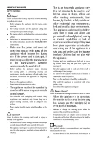
4 IMPORTANT PRECAUTIONS AND RECOMMENDATIONS After having unpacked the appliance, check to ensure that it is not damaged.In case of doubt, do not use it and consult your supplier or a professionally qualified techni-cian.Packing elements (i.e. plastic bags, polystyrene foam, nails, packing straps, et...
DeLonghi Manuals
-
 DeLonghi EN640 B
User Manual
DeLonghi EN640 B
User Manual
-
 DeLonghi EN640 W
User Manual
DeLonghi EN640 W
User Manual
-
 DeLonghi ENV95
User Manual
DeLonghi ENV95
User Manual
-
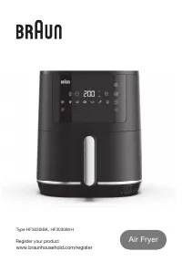 DeLonghi HF3030IBK
User Manual
DeLonghi HF3030IBK
User Manual
-
 DeLonghi EXAM440 55 B
Manual
DeLonghi EXAM440 55 B
Manual
-
 DeLonghi KG210
User Manual
DeLonghi KG210
User Manual
-
DeLonghi KG210
Manual
-
 DeLonghi CGH1112DP
User Manual
DeLonghi CGH1112DP
User Manual
-
 DeLonghi NSM 11 XL
User Manual
DeLonghi NSM 11 XL
User Manual
-
DeLonghi NSM 7 NL
User Manual
-
 DeLonghi ENV90
Manual
DeLonghi ENV90
Manual
-
DeLonghi ENV90
User Manual
-
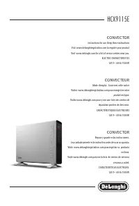 DeLonghi HCX9115E
User Manual
DeLonghi HCX9115E
User Manual
-
DeLonghi HCX9115E
Manual
-
DeLonghi HCX9115E
Installation Manual
-
 DeLonghi HFX60O15L
Manual
DeLonghi HFX60O15L
Manual
-
 DeLonghi TRLS0715EL
Manual
DeLonghi TRLS0715EL
Manual
-
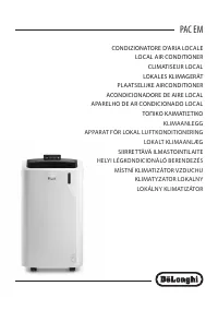 DeLonghi PAC EM93
User Manual
DeLonghi PAC EM93
User Manual
-
 DeLonghi EC230 BK
Manual
DeLonghi EC230 BK
Manual
-
DeLonghi EC230 BK
User Manual