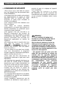
Page 4 - CONSIGNES DE SÉCURITÉ; ou; Attention; Les conditions de réglage sont
4 CONSIGNES DE SÉCURITÉ CONSIGNES DE SÉCURITÉ — — Nous avons conçu cette table de cuissonpour une utilisation par des particuliers dansun lieu d’habitation.— — Cet appareil doit être installé conformémentaux règlementations en vigueur et utiliséseulement dans un endroit bien aéré.Consultez ce guide ...
Page 5 - Votre appareil contient également; RESPECT DE L’ENVIRONNEMENT
5 RESPECT DE L’ENVIRONNEMENT • • — Les matériaux d’emballage de cet appareilsont recyclables. Participez à leur recyclageet contribuez ainsi à la protection del’environnement en les déposant dans lesconteneurs municipaux prévus à cet effet. Votre appareil contient également de nombreux matériauxrecy...
Page 6 - DESCRIPTION DE VOTRE APPAREIL; DESCRIPTION DE VOTRE TABLE; Conseil
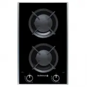
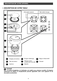
6 DESCRIPTION DE VOTRE APPAREIL • • DESCRIPTION DE VOTRE TABLE A B Chapeau de brûleur Tête de brûleur Injecteur C D Bougie d’allumage Thermocouple(modèle avec sécurité) Manette E F G H Bague d’étanchéité Robinet Conseil Ce guide d’installation et d’utilisation est valable pour plusieurs modèles. De ...
Page 7 - / INSTALL ATION DE VOTRE APPAREIL; CHOIX DE L’EMPLACEMENT
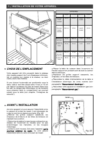
7 1 / INSTALL ATION DE VOTRE APPAREIL • • CHOIX DE L’EMPLACEMENT Votre appareil doit être encastré dans le plateaud'un meuble support de 3 cm d'épaisseur minimum,fait en matière qui résiste à la chaleur, ou bienrevêtu d'une telle matière. Si une cloison horizontale est positionnée sous latable, cell...
Page 8 - CONSEILS D’ENCASTREMENT; RACCORDEMENT ELECTRIQUE
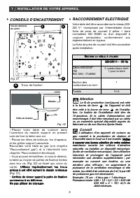
8 A A A A — Placez votre table de cuisson dansl’ouverture du meuble support en prenantsoin de tirer la table vers soi.— Placez les têtes de brûleurs, les chapeaux,et les grilles support casserole.Raccordez votre table au gaz (voir chapitre“Raccordement gaz”) et à l’électricité (voirchapitre “Raccord...
Page 9 - vissables (conforme à la norme; RACCORDEMENT GAZ; • Remarques préliminaires
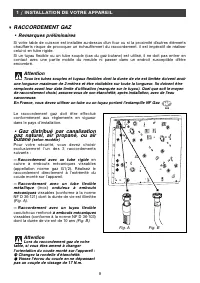
9 Le raccordement gaz doit être ef fectuéconformément aux règlements en vigueurdans le pays d’installation. • Gaz distribué par canalisation gaz naturel, air propané, ou air butané (selon modèle) Pour votre sécurité, vous devez choisirexclusivement l’un des 3 raccordementssuivants : — Raccordement a...
Page 10 - Gaz distribué par bouteille ou
10 1 / INSTALL ATION DE VOTRE APPAREIL • Gaz distribué par bouteille ou réservoir (gaz butane/propane) Pour votre sécurité, vous devez choisirexclusivement l’un des 3 raccordementssuivants : — Raccordement avec un tube rigide en cuivre à embouts mécaniques vissables(appellation norme gaz G1/2). Réal...
Page 11 - CHANGEMENT DE GAZ; Votre appareil est livré pré-réglé pour; Ne pas dépasser cette limite sous; A chaque changement de gaz, cochez; En France, cette table est également
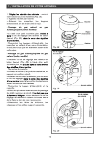
11 1 / INSTALL ATION DE VOTRE APPAREIL CHANGEMENT DE GAZ Attention Votre appareil est livré pré-réglé pour le gaz naturel.Les injecteurs nécessaires à l’adaptation aubutane/propane sont dans la pochettecontenant ce guide. A chaque changement de gaz, vous devrezsuccessivement : — Adapter le raccordem...
Page 13 - CHANGEMENT DE GAZ SUR LE BRULEUR TRIPLE COURONNE
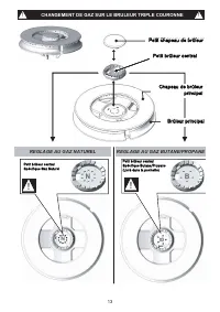
13 CHANGEMENT DE GAZ SUR LE BRULEUR TRIPLE COURONNE REGLAGE AU GAZ NATUREL REGLAGE AU GAZ BUTANE/PROPANE G N Petit Chapeau de brûleur B U T !! Chapeau de brûleur principal Brûleur principal !! !! !! Petit brûleur central Petit brûleur central N B Petit brûleur centralSpécifique Butane/Propane (Livré...
Page 14 - • Repérage des injecteurs
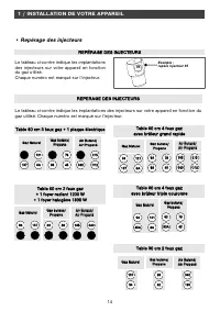
14 1 / INSTALL ATION DE VOTRE APPAREIL • Repérage des injecteurs Le tableau ci-contre indique les implantationsdes injecteurs sur votre appareil en fonctiondu gaz utilisé. Chaque numéro est marqué sur l’injecteur. Le tableau ci-contre indique les implantations des injecteurs sur votre appareil en fo...
Page 15 - •Caractéristiques gaz
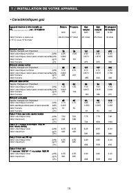
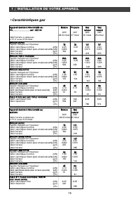
15 1 / INSTALL ATION DE VOTRE APPAREIL •Caractéristiques gaz A Ap pp pa arre eiill d de es sttiin né é à à ê êttrre e iin ns stta allllé é e en n :: B Bu utta an ne e P Prro op pa an ne e G Ga azz G Ga azz A Aiirr p prro op pa an né é F FR R..............................................................
Page 17 - / UTILISATION DE VOTRE APPAREIL; DESCRIPTION DE VOTRE DESSUS
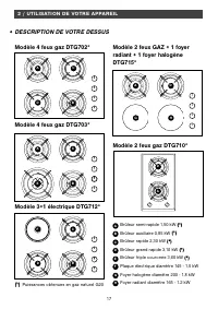
17 2 / UTILISATION DE VOTRE APPAREIL DESCRIPTION DE VOTRE DESSUS • • Modèle 4 feux gaz DTG702* Modèle 2 feux gaz DTG710* Modèle 3+1 électrique DTG712* Modèle 2 feux GAZ + 1 foyerradiant + 1 foyer halogèneDTG715* A B C D E F G H Brûleur semi-rapide 1,50 kW ((* *)) Brûleur auxiliaire 0,85 kW ((* *)) B...
Page 18 - MISE EN MARCHE DES; ” correspond à la fermeture du; Lorsqu’une manette devient difficile à
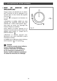
18 2 / UTILISATION DE VOTRE APPAREIL MISE EN MARCHE DES BRULEURS GAZ Chaque brûleur est alimenté par un robinet,dont l’ouverture se fait en appuyant et entournant dans le sens inverse des aiguillesd’une montre.Le point “ ● ” correspond à la fermeture du robinet.— — Choisissez le brûleur désiré en vo...
Page 19 - REGLAGE DE LA MINUTERIE; En cas de coupure de courant, le; Lorsque le temps est écoulé,
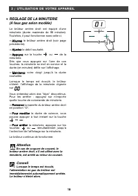
19 19 2 / UTILISATION DE VOTRE APPAREIL REGLAGE DE LA MINUTERIE (4 feux gaz selon modèle) Le brûleur arrière droit est équipé d’uneminuterie (durée maximale de 99 minutes).Toutefois, il peut fonctionner sans celle-ci. — A Allllu um me ezz le brûleur arrière droit (voir page précédente). — A Ajju us ...
Page 20 - RECIPIENTS ADAPTES POUR LES BRULEURS GAZ; • Quel brûleur utiliser en fonction de votre récipient ?; Maintenez ouverts les orifices
20 2 / UTILISATION DE VOTRE APPAREIL • • B BO ON N M MA AU UV VA AIIS S C CO ON NV VE EX XE E C CO ON NC CA AV VE E Fig. 01 Fig. 02 Fig. 03 RECIPIENTS ADAPTES POUR LES BRULEURS GAZ • Quel brûleur utiliser en fonction de votre récipient ? — Réglez la couronne de flammes de façonque celles-ci ne débor...
Page 21 - RECIPIENTS ADAPTES SUR LA; en acier inoxydable avec fond trimétal épais; MISE EN MARCHE DE LA PLAQUE; Utilisez un récipient de taille; Ne laissez pas fonctionner un foyer; La plaque électrique reste chaude un
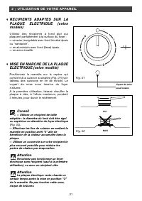
21 2 / UTILISATION DE VOTRE APPAREIL RECIPIENTS ADAPTES SUR LA PLAQUE ELECTRIQUE (selon modèle) Utilisez des récipients à fond plat quiplaquent parfaitement à la surface du foyer : — en acier inoxydable avec fond trimétal épais ou “sandwich”, — en aluminium avec fond (lisse) épais, — en acier émaill...
Page 22 - MISE EN MARCHE DES FOYERS
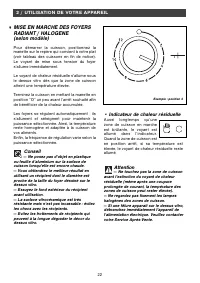
22 • Indicateur de chaleur résiduelle Aussi longtemps qu’unezone de cuisson en marcheest brûlante, le voyant estallumé dans l’indicateur.Quand la zone de cuisson esten position arrêt, si sa température estélevée, le voyant de chaleur résiduelle resteallumé. Attention — Ne touchez pas la zone de cuis...
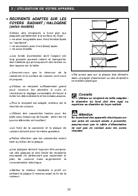
Page 23 - Conseils; Utilisez un récipient de taille adaptée :; RECIPIENTS ADAPTES SUR LES
23 2 / UTILISATION DE VOTRE APPAREIL — — Ne posez pas sur la plaque des alimentsdans un papier d’aluminium ou des récipientsen matière plastique. Conseils Utilisez un récipient de taille adaptée : le diamètre du fond doit être égal ousupérieur au diamètre du foyer radiant. Attention En branchant des...
Page 24 - N’utilisez pas de nettoyeur vapeur.; ENTRETENIR VOTRE APPAREIL; / ENTRETIEN COURANT DE VOTRE APPAREIL
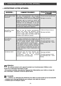
24 Attention - Ne nettoyez jamais votre appareil pendant son fonctionnement. Mettez à zéro toutes les commandes électriques et gaz.- Si la surface est fêlée, déconnectez l’appareil de l’alimentation pour éviter un risque dechoc électrique. Contactez le Service Après-Vente. Conseils — Préférez un net...
Page 25 - EN COURS D’UTILISATION
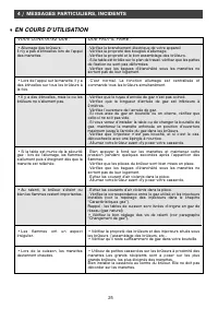
25 4 / MESSAGES PARTICULIERS, INCIDENTS EN COURS D’UTILISATION • • VOUS CONSTATEZ QUE : QUE FAUT-IL FAIRE : . Vérifiez le branchement électrique de votre appareil. Vérifiez la propreté des bougies d’allumage.. Vérifiez la propreté et le bon assemblage des brûleurs.. Si la table est bridée sur le pla...
Page 26 - / TABLEAU DE CUISSON; GUIDE DE CUISSON GAZ
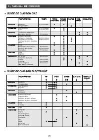
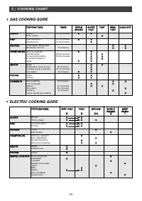
26 5 / TABLEAU DE CUISSON GUIDE DE CUISSON GAZ • • P PR RE EP PA AR RA AT TIIO ON NS S T TE EM MP PS S T TR RIIP PL LE E G GR RA AN ND D R RA AP PIID DE E S SE EM MII-- A AU UX XIIL LIIA AIIR RE E C CO OU UR RO ON NN NE E R RA AP PIID DE E R RA AP PIID DE E S SO OU UP PE ES S Bouillons 8-10 minutes ...
Page 27 - GUIDE DE CUISSON RADIANT / HALOGENE
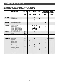
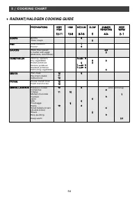
27 5 / TABLEAU DE CUISSON GUIDE DE CUISSON RADIANT / HALOGENE • • P PR RE EP PA AR RA AT TIIO ON NS S T TR RE ES S V VIIF F V VIIF F M MO OY YE EN N L LE EN NT T M MIIJJO OT TA AG GE E-- T TE EN NIIR R R RE EC CH HA AU UF FF FA AG GE E A AU U C CH HA AU UD D 1 12 2--1 11 1 1 10 0--9 9 8 8--7 7--6 6 ...
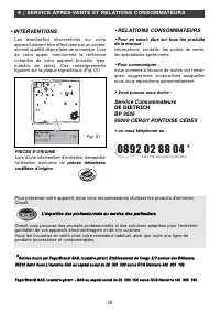
Page 28 - •INTERVENTIONS; / SERVICE APRES-VENTE ET REL ATIONS CONSOMMATEURS; •RELATIONS CONSOMMATEURS; •Pour en savoir plus sur tous les produits; Service Consommateurs; DE DIETRICH
28 Les éventuelles inter ventions sur votre appareil doivent être effectuées par un profes-sionnel qualifié dépositaire de la marque. Lorsde votre appel, mentionnez la référencecomplète de votre appareil (modèle, type,numéro de série). Ces renseignementsfigurent sur la plaque signalétique (Fig. 01)....
Page 30 - TABLE OF CONTENTS
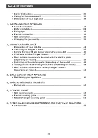
30 TABLE OF CONTENTS • • Safety Instructions _________________________________________ 31 • • Caring for the environment __________________________________ 32• • Description of your appliance ________________________________ 33 1 / INSTALLING YOUR APPLIANCE • • Choice of location ___________________...
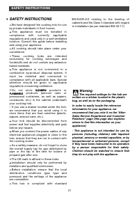
Page 31 - SAFETY INSTRUCTIONS; — Do not store; Warning; The required settings for the hob are
31 SAFETY INSTRUCTIONS SAFETY INSTRUCTIONS — — We have designed this cooking hob for useby private individuals in their homes.— — This appliance must be installed incompliance with currently applicableregulations and used only in a well-ventilatedlocation. Consult this guide before installingand usi...
Page 32 - CARING FOR THE ENVIRONMENT
32 CARING FOR THE ENVIRONMENT • • — This appliance’s packing materials arerecyclable. Recycle them and play a role inprotecting the environment by depositingthem in local authority containers providedfor this purpose. Your appliance also containsvarious recyclable materials. It istherefore marked wi...
Page 33 - DESCRIPTION OF YOUR APPLIANCE; DESCRIPTION OF THE HOB; Tip
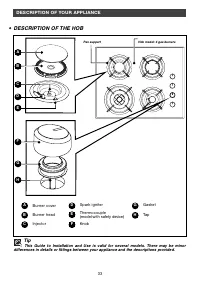
33 DESCRIPTION OF YOUR APPLIANCE • • DESCRIPTION OF THE HOB A B Burner cover Burner head Injector C D Spark igniter Thermocouple(model with safety device) Knob E F G H Gasket Tap Tip This Guide to Installation and Use is valid for several models. There may be minor differences in details or fittings...
Page 34 - / INSTALLING YOUR APPLIANCE; CHOICE OF LOCATION
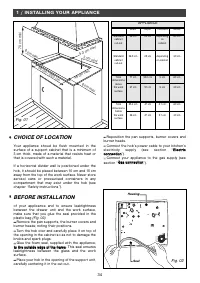
34 1 / INSTALLING YOUR APPLIANCE • • CHOICE OF LOCATION Your appliance shoud be flush mounted in thesurface of a support cabinet that is a minimum of3 cm thick, made of a material that resists heat orthat is covered with such a material. If a horizontal divider wall is positioned under thehob, it sh...
Page 35 - FITTING TIPS; ELECTRIC CONNECTION
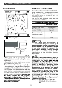
35 A A A A — Place your hob in the opening of thesupport cabinet, carefully pulling the tabletowards you.— Reposition the burner heads, burner coversand pan supports on the hob.Connect your hob to the gas supply (See“Gas Connection” chapter) and to the powersupply (See “Electrical Connection” chapte...
Page 36 - Natural gas supplied by pipe,; made from; GAS CONNECTION; • Preliminary comments
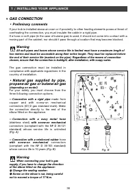
36 The gas connection must be installed incompliance with applicable regulations in thecountry of installation. • Natural gas supplied by pipe, propane-air gas or butane-air gas (depending on model) For your safety, you must choose from thethree following connection options: — Connection with a rigi...
Page 37 - Gas supplied by tank or
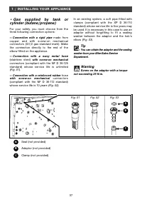
37 1 / INSTALLING YOUR APPLIANCE • Gas supplied by tank or cylinder (butane/propane) For your safety, you must choose from thethree following connection options: — Connection with a rigid pipe made from copper and with screw -on mechanicalconnectors (G1/2 gas standard mark). Makethe connection direc...
Page 38 - CHANGING THE GAS SUPPLY; Your appliance is sold pre-set for; Exceeding this limit may damage the; Each time you change the gas supply,
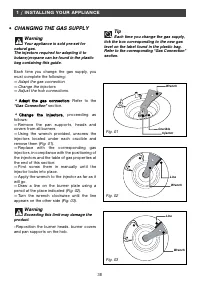
38 1 / INSTALLING YOUR APPLIANCE CHANGING THE GAS SUPPLY Warning Your appliance is sold pre-set for natural gas.The injectors required for adapting it tobutane/propane can be found in the plasticbag containing this guide. Each time you change the gas supply, youmust complete the following: — Adapt t...
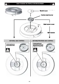
Page 40 - GAS CHANGE ON TRIPLE-CROWN BURNER
40 CHANGEMENT DE GAZ SUR LE BRULEUR TRIPLE COURONNE REGLAGE AU GAZ NATUREL REGLAGE AU GAZ BUTANE/PROPANE G N Petit Chapeau de brûleur B U T !! Chapeau de brûleur principal Brûleur principal !! !! !! Petit brûleur central Petit brûleur central N B Petit brûleur centralSpécifique Butane/Propane (Livré...
Page 41 - • Markings on the injectors
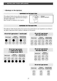
41 1 / INSTALLING YOUR APPLIANCE • Markings on the injectors The adjacent table shows where the injectorsare positioned on your appliance according tothe type of gas used. Each number is marked on the injector. The adjacent table shows where the injectors are positioned on your appliance according t...
Page 42 - •Gas Properties
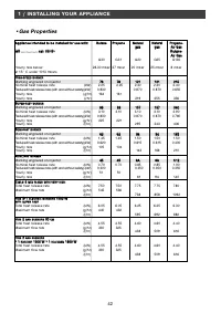
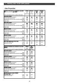
42 1 / INSTALLING YOUR APPLIANCE •Gas Properties A Ap pp plliia an nc ce e iin ntte en nd de ed d tto o b be e iin ns stta alllle ed d ffo orr u us se e w wiitth h:: B Bu uttaan ne e P Prro op paan ne e N Naattu urraall N Naattu urraall P Prro op paan ne e-- g ga as s g ga as s A Aiirr G Gaass G GB ...
Page 44 - / USING YOUR APPLIANCE; DESCRIPTION OF YOUR HOB TOP
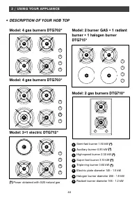
44 2 / USING YOUR APPLIANCE DESCRIPTION OF YOUR HOB TOP • • Model: 4 gas burners DTG702* Model: 2 gas burners DTG710* Model: 3+1 electric DTG712* Model: 2 burner GAS + 1 radiantburner + 1 halogen burnerDTG715* A B C D E F G H Semi-fast burner 1.50 kW ((* *)) Auxiliary burner 0.85 kW ((* *)) High-spe...
Page 45 - SWITCHING ON THE GAS; ” corresponds to a closed tap.; When a knob becomes difficult to turn,
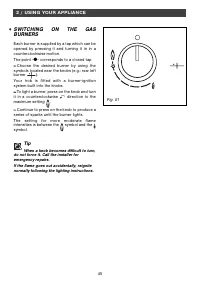
45 2 / USING YOUR APPLIANCE SWITCHING ON THE GAS BURNERS Each burner is supplied by a tap which can beopened by pressing it and turning it in in acounterclockwise motion.The point “ ● ” corresponds to a closed tap. — — Choose the desired burner by using thesymbols located near the knobs (e.g.: rear ...
Page 46 - SETTING THE TIMER; In the case of a power cut, the right; When the time has run out, the gas
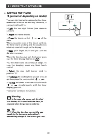
46 2 / USING YOUR APPLIANCE SETTING THE TIMER (4 gas burner depending on model) The rear right burner is equipped with a timer(maximum duration 99 minutes). However, itcan work without this. — L Liig gh htt the rear right burner (see previous section). — A Ad djju us stt the flame desired. — P Prre ...
Page 47 - COOKWARE SUITABLE FOR GAS BURNERS; • Which burner should you use depending on your cookware?; Keep natural ventilation orifices in
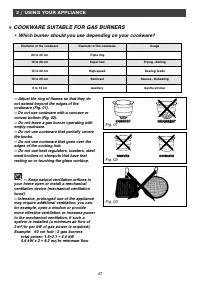
47 2 / USING YOUR APPLIANCE • • C CO OR RR RE EC CT T IIN NC CO OR RR RE EC CT T C CO ON NV VE EX X C CO ON NC CA AV VE E Fig. 01 Fig. 02 Fig. 03 COOKWARE SUITABLE FOR GAS BURNERS • Which burner should you use depending on your cookware? — Adjust the ring of flames so that they donot extend beyond t...
Page 48 - MOST SUITABLE COOKWARE TO; in stainless steel with a thick, three-metal or; SWITCHING ON THE ELECTRIC; — Use cookware of an appropriate size:; Do not operate an electric cooking; The electric plate will remain hot for a
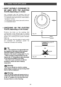
48 2 / USING YOUR APPLIANCE MOST SUITABLE COOKWARE TO BE USED WITH THE ELECTRIC PLATE (depending on model) Use cookware with flat bottoms that areperfectly flush with the surface of the burner: — in stainless steel with a thick, three-metal or “sandwich” bottom, — in aluminium with a thick (smooth) ...
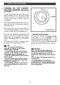
Page 49 - — Do not touch the cooking zone; TURNING ON THE RADIANT/; — Do not place any plastic or
49 • Residual heat indicator As long as a cooking zonebeing used is hot, theindicator light stays on. Whena cooking zone is in the offposition but its temperatureis high, the residual heat indicator remainson. Warning — Do not touch the cooking zone before the residual heat indicator goes off(or aft...
Page 50 - Tips; Use cookware of an appropriate size:; MOST SUITABLE COOKWARE
50 2 / USING YOUR APPLIANCE — — Do not place any food in aluminium foil or inplastic containers on the plate. Tips Use cookware of an appropriate size: the diameter of the bottom of the cookwareshould be equal to or greater than thediameter of the radiant plate Warning When you connect the power cab...
Page 51 - / DAILY CARE OF YOUR APPLIANCE; MAINTAINING YOUR APPLIANCE
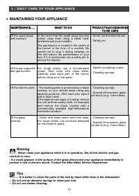
51 3 / DAILY CARE OF YOUR APPLIANCE Warning - Never clean your appliance while it is in operation. Set all the electric and gas controls to zero.- If a crack appears in the surface of the glass disconnect your appliance immediately toprevent a risk of electric shock. Contact the After-Sales Service ...
Page 52 - DURING USE
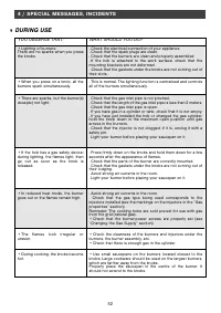
52 4 / SPECIAL MESSAGES, INCIDENTS DURING USE • • YOU OBSERVE THAT: WHAT SHOULD YOU DO? . Check the electrical connection of your appliance. Check that the spark plugs are clean.. Check that the burners are clean and properly assembled. If the hob is attached to the work surface, check that themount...
Page 54 - RADIANT/HALOGEN COOKING GUIDE
54 5 / COOKING CHART RADIANT/HALOGEN COOKING GUIDE • • P PR RE EP PA AR RA AT TIIO ON NS S V VE ER RY Y H HIIG GH H M ME ED DIIU UM M S SL LO OW W S SIIM MM ME ER R K KE EE EP P H HIIG GH H R RE EH HE EA AT TIIN NG G W WA AR RM M 1 12 2--1 11 1 1 10 0--9 9 8 8--7 7--6 6 5 5 4 4--3 3-- 2 2-- 1 1 S SO...
Page 55 - • SERVICE CALLS; / AFTER-SALES SERVICE DEPARTMENT AND CUSTOMER REL ATIONS
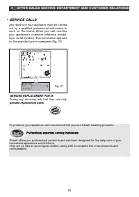
55 Any repairs to your appliance must be carried out by a qualified professional authorised towork on the brand. When you call, mentionyour appliance’s complete reference (model,type, serial number). This information appearson the manufacturer’s nameplate (Fig. 01). GENUINE REPLACEMENT PARTS During ...


 De Dietrich DPE7929XF
User Manual
De Dietrich DPE7929XF
User Manual
 De Dietrich DPI7360X
User Manual
De Dietrich DPI7360X
User Manual
 De Dietrich DPI7540B
User Manual
De Dietrich DPI7540B
User Manual
 De Dietrich DPI7572G
User Manual
De Dietrich DPI7572G
User Manual
 De Dietrich DPI7572X
User Manual
De Dietrich DPI7572X
User Manual
 De Dietrich DPI7602BM
User Manual
De Dietrich DPI7602BM
User Manual
 De Dietrich DPI7670X
User Manual
De Dietrich DPI7670X
User Manual
 De Dietrich DPI7670XU
User Manual
De Dietrich DPI7670XU
User Manual
 De Dietrich DPI7684X
User Manual
De Dietrich DPI7684X
User Manual
 De Dietrich DPI7768X
User Manual
De Dietrich DPI7768X
User Manual
 De Dietrich DPI7884W
User Manual
De Dietrich DPI7884W
User Manual
 De Dietrich DTG 1008 X
User Manual
De Dietrich DTG 1008 X
User Manual
 De Dietrich DTI 1113 X
User Manual
De Dietrich DTI 1113 X
User Manual
 De Dietrich DTI 1167 XE
User Manual
De Dietrich DTI 1167 XE
User Manual
 De Dietrich DTI 1358 DG
User Manual
De Dietrich DTI 1358 DG
User Manual