Daikin DCM601A72- Manuals
Daikin DCM601A72– Installation Manual in PDF format online.
Manuals:
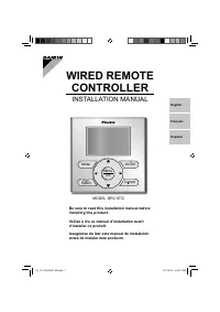
Installation Manual Daikin DCM601A72


Summary
Disclosure To the User in USA Part 15 of FCC Note: This equipment has been tested and found to comply with the limits for a Class B digital device, pursuant to part 15 of the FCC Rules. These limits are designed to provide reasonable protection against harmful interference in a residential installat...
Installation Manual 3P291714-4B DCM601A72 iTM plus adaptor 3 English All phases of the field-installation, including, but not limited to, electrical, piping, safety, etc. must be in accordance with manufacturer’s instructions and must comply with national, state, provincial and local codes. Read the...
4 Installation Manual 3P291714-4B DCM601A72 iTM plus adaptor English CAUTION • Keep water out of the controller. • To avoid electric shock due to entry of water or insects, fill the wiring through- hole with putty. • Do not wash the controller with water as it may result in electrical shocks or fire...
Daikin Manuals
-
 Daikin 3MXS68G2V1B
Installation Manual
Daikin 3MXS68G2V1B
Installation Manual
-
 Daikin 4MXS68F2V1B
User Manual
Daikin 4MXS68F2V1B
User Manual
-
 Daikin Altherma HT
Installation Manual
Daikin Altherma HT
Installation Manual
-
 Daikin ARC433B46
User Manual
Daikin ARC433B46
User Manual
-
 Daikin ARC433B47
User Manual
Daikin ARC433B47
User Manual
-
 Daikin Altherma LT
User Manual
Daikin Altherma LT
User Manual
-
 Daikin ATXD60CV4
User Manual
Daikin ATXD60CV4
User Manual
-
 Daikin BRC1E52A
User Manual
Daikin BRC1E52A
User Manual
-
 Daikin BRC1E52A7
Installation Manual
Daikin BRC1E52A7
Installation Manual
-
 Daikin BRC1E51A7
User Manual
Daikin BRC1E51A7
User Manual
-
 Daikin BRC1E61
User Manual
Daikin BRC1E61
User Manual
-
 Daikin BRC1E72
Installation Manual
Daikin BRC1E72
Installation Manual
-
 Daikin BRC230Z4
User Manual
Daikin BRC230Z4
User Manual
-
 Daikin BRC24Z8
User Manual
Daikin BRC24Z8
User Manual
-
 Daikin DCS302C71
Installation Manual
Daikin DCS302C71
Installation Manual
-
 Daikin EBLQ036BA6VJU1
Installation Manual
Daikin EBLQ036BA6VJU1
Installation Manual
-
 Daikin EGSQH10S18AA9W
User Manual
Daikin EGSQH10S18AA9W
User Manual
-
 Daikin EHYKOMB33AA
User Manual
Daikin EHYKOMB33AA
User Manual
-
 Daikin EKHBH016AB
Installation Manual
Daikin EKHBH016AB
Installation Manual
-
 Daikin ERLQ054BAVJU
User Manual
Daikin ERLQ054BAVJU
User Manual