Cub Cadet 1X 21" LHP - Manuals

User Manual Cub Cadet 1X 21" LHP


Summary
Important Safe Operation Practices 1 2 WARNING! This symbol points out important safety instructions which, if not followed, could endanger the personal safety and/or property of yourself and others. Read and follow all instructions in this manual before attempting to operate the equipment. Failure ...
3 S ection 1 — i mportant S afe o peration p racticeS 8. Exercise extreme caution when operating on or crossing gravel surfaces. Stay alert for hidden hazards or traffic. 9. Exercise caution when changing direction and while operating on slopes. Do not operate on steep slopes. 10. Plan your snow-thr...
4 S ection 1 — i mportant S afe o peration p racticeS Safety Symbols This page depicts and describes safety symbols that may appear on this product. Read, understand, and follow all instructions on the machine before attempting to assemble and operate. Symbol Description READ THE OPERATOR’S MANUAL(S...
Cub Cadet Snow Blowers Manuals
-
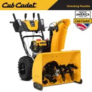
 Cub Cadet 2X 24 IP
User Manual
Cub Cadet 2X 24 IP
User Manual
-
 Cub Cadet 2X 26 IP
User Manual
Cub Cadet 2X 26 IP
User Manual
-
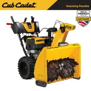
 Cub Cadet 2X 26 TRAC IP
User Manual
Cub Cadet 2X 26 TRAC IP
User Manual
-
 Cub Cadet 2X 28 IP
User Manual
Cub Cadet 2X 28 IP
User Manual
-
 Cub Cadet 2X 30 EFI
User Manual
Cub Cadet 2X 30 EFI
User Manual
-
 Cub Cadet 2X 30 MAX
User Manual
Cub Cadet 2X 30 MAX
User Manual
-
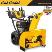 Cub Cadet 3X 28"
User Manual
Cub Cadet 3X 28"
User Manual
-
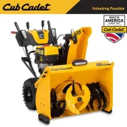
 Cub Cadet 3X 30 HD
User Manual
Cub Cadet 3X 30 HD
User Manual
-
 Cub Cadet 3X 30 TRAC w/LED Light Bar
User Manual
Cub Cadet 3X 30 TRAC w/LED Light Bar
User Manual
-
 Cub Cadet 3X 30" MAX EFI IntelliPower
User Manual
Cub Cadet 3X 30" MAX EFI IntelliPower
User Manual
-
 Cub Cadet 3X 34" MAX Hydro EFI IntelloPower
User Manual
Cub Cadet 3X 34" MAX Hydro EFI IntelloPower
User Manual