Best CPD9M363SB - Manuals
Best CPD9M363SB Range Hood – User Manual in PDF format online.
Manuals:
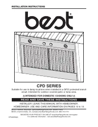
User Manual Best CPD9M363SB


Summary
2 TO REDUCE THE RISK OF FIRE, ELECTRIC SHOCK OR INJURY TO PERSONS, OBSERVE THE FOLLOWING: 1. Use this unit only in the manner intended by the manufacturer. If you have questions, contact the manufacturer at the address or telephone number listed in the warranty. 2. Before servicing or cleaning unit,...
3 These power packs must be installed with the P12NA blower (sold separately). Do not substitute for an other blower. Plan where and how the ductwork will be installed. A straight, short duct run will allow the hood to perform most efficiently. Install 10-inch ductwork, elbows and roof or wall cap. ...
4 3. CUSTOM HOOD PREPARATION WARNING ! When building a custom hood, always follow all applicable construction codes and standards. The custom hood must be constructed to fit the size and shape of the power pack. See chart and illustration below for details. S IZE T OTAL WEIGHT P OWER PACK WIDTH (A)*...
Best Range Hoods Manuals
-
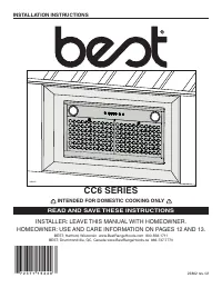 Best CC65I28SB
User Manual
Best CC65I28SB
User Manual
-
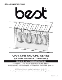 Best CP34I429SB
User Manual
Best CP34I429SB
User Manual
-
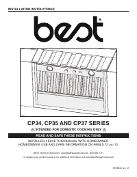 Best CP35I309SB
User Manual
Best CP35I309SB
User Manual
-
Best CP35I369SB
User Manual
-
Best CP35I429SB
User Manual
-
Best CP37I482SB
User Manual
-
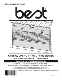 Best CP55IQ369SB
User Manual
Best CP55IQ369SB
User Manual
-
Best CP55IQ429SB
User Manual
-
Best CP57E362SB
User Manual
-
Best CP57E482SB
User Manual
-
Best CP57E602SB
User Manual
-
Best CP57IQT369SB
User Manual
-
Best CP57IQT482SB
User Manual
-
Best CP57IQT489SB
User Manual
-
Best CP57IQT542SB
User Manual
-
Best CP57IQT602SB
User Manual
-
Best CP57IQT662SB
User Manual
-
 Best CPDI362SB
User Manual
Best CPDI362SB
User Manual
-
Best CPDI482SB
User Manual
-
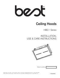 Best HBC143ESS
User Manual
Best HBC143ESS
User Manual