Page 2 - TO REDUCE THE RISK OF A RANGE TOP GREASE FIRE:; WARNING
2 TO REDUCE THE RISK OF FIRE, ELECTRIC SHOCK OR INJURY TO PERSONS, OBSERVE THE FOLLOWING: 1. Use this unit only in the manner intended by the manufacturer. If you have questions, contact the manufacturer at the address or telephone number listed in the warranty. 2. Before servicing or cleaning unit,...
Page 4 - PREPARE INSTALLATION; INSTALL DUCTWORK AND ELECTRICAL WIRING; CUSTOM HOOD PREPARATION
4 1. PREPARE INSTALLATION Plan where and how the ductwork will be installed. Access to the top of the hood is preferred for connection of ductwork. Install proper-sized ductwork, elbows and roof or wall cap for the type of blower you are installing. If installing CP34 or CP35 power pack, use 8” roun...
Page 5 - CONT; MOUNT CUSTOM HOOD INTERNAL FRAMEWORK
5 3. CUSTOM HOOD PREPARATION ( CONT ’ D ) To minimize the gap around the power pack, take actual width and depth measurements of power pack and add 1/16” to get D and E measurements. Cut the hole in the bottom of the cabinet according to dimensions. See chart and illustration for details. 4. MOUNT C...
Page 6 - REMOVE GREASE DRIP RAIL; REMOVE BOTTOM PANEL
6 6. REMOVE GREASE DRIP RAIL A. Lift grease drip rail to disengage it from the bottom panel. B. Slide grease rail all the way to the left or right ( ) and lift the opposite end to disengage the other end from the bottom panel ( ). Remove it from the power pack and set aside for later use. 7. REM...
Page 7 - DO NOT FORGET TO CONNECT THE GROUND
7 10. INSTALL ADAPTER AND DAMPER (CP37 MODEL ONLY) Using 2 no. 8 x 3/8” screws from parts bag, assemble the adapter on the top of the power pack. Seal all joints with metal foil duct tape to eliminate air leaks. Install 10” damper inside the VERTICAL ductwork that will be attached to power pack. Do ...
Page 9 - INSTALL POWER PACK; CAUTION; Take care not to kink ducting when installing the power pack.
9 13. INSTALL POWER PACK CAUTION Take care not to kink ducting when installing the power pack. Using provided no. 8 x 1/2” chrome plated screws, install the power pack inside the custom hood. Start with 2 screws on front corners, then use 4 screws for sides and use the remaining ones to finalize sec...
Page 10 - REINSTALL BOTTOM PANEL; REINSTALL GREASE DRIP RAIL
10 14. REINSTALL BLOWER(S) ( CONT ’ D ) Plug the blower(s) in. HE0085 A LL MODELS 15. REINSTALL BOTTOM PANEL Lift the bottom panel and engage the power pack metal tabs in bottom panel slots, as shown in details A and B below. Secure the bottom panel to the power pack using its screws previously remo...
Page 11 - REINSTALL BAFFLE FILTERS
11 17. REINSTALL BAFFLE FILTERS CAUTION Remove protective plastic film covering filters before installing them. It is recommended to install side filters first and finish with center one(s). 1. Insert one end of the filter into the upper channel of the power pack. 2. Raise the other end toward the i...
Page 12 - Avoid when choosing a detergent:
12 19. USE AND CARE Baffle Filters The baffle filters should be cleaned frequently. Use a warm detergent solution. Wash more often if your cooking style generates greater grease — like frying foods or wok cooking. Remove baffle filters by pushing them towards the back of hood and rotating filters do...
Page 14 - ONE-YEAR LIMITED WARRANTY; Best
14 21. WARRANTY ONE-YEAR LIMITED WARRANTY Broan-NuTone LLC (“Broan-NuTone”) warrants to the original consumer purchaser of its products that such products will be free from defects in materials or workmanship for a period of one year from the date of original purchase. THERE ARE NO OTHER WARRANTIES,...
Page 17 - INSTALLATEUR : LAISSER CE GUIDE AU PROPRIÉTAIRE.; LIRE ET CONSERVER CES DIRECTIVES
SÉRIES CP34, CP35 ET CP37 HB0078 GUIDE D’INSTALLATION CONÇUES POUR USAGE DOMESTIQUE SEULEMENT INSTALLATEUR : LAISSER CE GUIDE AU PROPRIÉTAIRE. PROPRIÉTAIRE : DIRECTIVES D’UTILISATION ET D’ENTRETIEN EN PAGES 28 ET 29. LIRE ET CONSERVER CES DIRECTIVES BEST; Hartford, Wisconsin www.BestRangeHoods.com 8...
Page 20 - PRÉPARER L’INSTALLATION; INSTALLER LES CONDUITS ET LE CÂBLAGE ÉLECTRIQUE; PRÉPARER L’ARMOIRE POUR HOTTE; AVERTISSEMENT
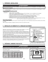
20 1. PRÉPARER L’INSTALLATION Déterminer à quel endroit et comment les conduits seront installés. Un accès au dessus de la hotte est préférable pour le raccordement des conduits. Installer des conduits de dimensions appropriées, coude(s) et capuchon de mur ou de toit selon le type de ventilateur. Po...
Page 21 - SUITE; ASSEMBLER LA CHARPENTE DE L’ARMOIRE; RETIRER LES FILTRES
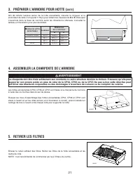
21 3. PRÉPARER L’ARMOIRE POUR HOTTE ( SUITE ) Afin de réduire l’espace autour de la hotte encastrable, mesurer la longueur et la profondeur de celle-ci et ajouter 1/16 po pour obtenir les mesures de D et E . Découper L'ouverture dans la base de l’armoire selon les dimensions obtenues. Consulter le t...
Page 22 - RETIRER LA GOUTTIÈRE; RETIRER LE PANNEAU INFÉRIEUR
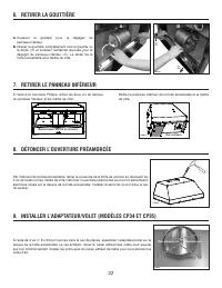
22 6. RETIRER LA GOUTTIÈRE A. Soulever la goutière pour la dégager du panneau inférieur. B. Glisser la gouttière complètement vers la gauche ou la droite ( ) et soulever l’extrémité opposée pour la dégager du panneau inférieur ( ). La retirer de la hotte encastrable et la mettre de côté. 7. RETI...
Page 23 - NE PAS OUBLIER DE CONNECTER LA MISE À LA TERRE
23 10. INSTALLER L’ADAPTATEUR ET LE VOLET (MODÈLE CP37 SEULEMENT) À l’aide de 2 vis n° 8 x 3/8 po fournies dans le sac de pièces, assembler l’adaptateur sur le dessus de la hotte encastrable. Sceller les joints avec du ruban adhésif de métal pour éliminer les fuites d’air. Installer le volet de 10 p...
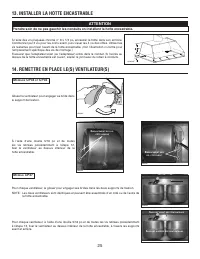
Page 25 - INSTALLER LA HOTTE ENCASTRABLE; ATTENTION
25 13. INSTALLER LA HOTTE ENCASTRABLE ATTENTION Prendre soin de ne pas gauchir les conduits en installant la hotte encastrable. À l’aide des vis plaquées chrome n° 8 x 1/2 po, encastrer la hotte dans son armoire. Commencer par 2 vis pour les coins avant, puis visser les 4 vis des côtés. Utiliser les...
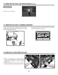
Page 26 - REMETTRE EN PLACE LE PANNEAU INFÉRIEUR; REMETTRE LA GOUTTIÈRE EN PLACE
26 14. REMETTRE EN PLACE LE(S) VENTILATEUR(S) ( SUITE ) Rebrancher le(s) ventillateur(s). HE0085 T OUS LES MODÈLES 15. REMETTRE EN PLACE LE PANNEAU INFÉRIEUR Soulever le panneau inférieur et engager les pattes de métal de la hotte dans les fentes du panneau inférieur, tel qu’il est illustré dans les...
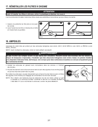
Page 27 - RÉINSTALLER LES FILTRES À CHICANE
27 17. RÉINSTALLER LES FILTRES À CHICANE ATTENTION Avant d’installer les filtres à chicane, retirer le plastique protecteur de ceux-ci. Il est recommandé d’installer d’abord les filtres situés aux extrémités et de terminer par le(s) filtre(s) du centre. 1. Insérer une extrémité du filtre dans le rai...
Page 30 - GARANTIE LIMITÉE DE UN AN
30 21. GARANTIE GARANTIE LIMITÉE DE UN AN Broan-NuTone LLC (« Broan-NuTone ») garantit à l’acheteur consommateur initial de ses produits qu’ils sont exempts de tout défaut dans les matières premières ou la main-d’œuvre, pour une période de un an à compter de la date d’achat par le consommateur initi...
Page 31 - SCHÉMA ÉLECTRIQUE
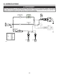
31 22. SCHÉMA ÉLECTRIQUE LIGNE NEUTRE MISE À LA TERRE 12 0 V C A B M BR BL R N M B COMMANDE DE VITESSE HS THERMOSTAT BL N BL N B B B B N N J J LAMPE INTERRUPTEUR D’ÉCLAIRAGE L 1 2 INTERRUPTEUR DU VENTILATEUR BL BL BL BL LAMPE CODE DE COULEUR HE0092F N B BLANCBL BLEUBR BRUNJ JAUNEN NOIRR ROUGE BR BL ...
Page 32 - PIÈCES DE REMPLACEMENT
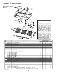
32 23. PIÈCES DE REMPLACEMENT Best séries CP34, CP35et CP37 HL0110 10 11 12 15 14 16 13 1 2 3 4 5 6 7 8 9 P IÈCES DE REMPLACEMENT ET SERVICE Pour assurer le bon fonctionnement de votre appareil, vous devez toujours utiliser des pièces d’origine provenant de Broan-NuTone. Les pièces d’origine de Broa...
Page 33 - INSTALADOR: ENTREGUE ESTE MANUAL AL PROPIETARIO DE LA CASA.; LEA ESTAS INSTRUCCIONES Y GUÁRDELAS
SERIES CP34, CP35 Y CP37 HB0078 INSTRUCCIONES DE INSTALACIÓN EXCLUSIVAMENTE PARA COCINAS DOMÉSTICAS INSTALADOR: ENTREGUE ESTE MANUAL AL PROPIETARIO DE LA CASA. PROPIETARIO: INFORMACIÓN SOBRE UTILIZACIÓN Y CUIDADO EN LAS PÁGINAS 44 Y 45. LEA ESTAS INSTRUCCIONES Y GUÁRDELAS BEST; Hartford, Wisconsin w...
Page 35 - - SISTEMAS CON EL GRUPO DE ALIMENTACIÓN -
35 HL0122 - SISTEMAS CON EL GRUPO DE ALIMENTACIÓN - CP34, CP35 Y CP37 M ODELO 634 O 644 (T APA DE TECHO ) M ODELO 643 (C APUCHÓN MURAL REDONDO DE 8”) M ODELO 418 (C ODO AJUSTABLE REDONDO DE 10”) M ODELO 410 (T UBO REDONDO DE 10”, SECCIONES DE 2 PIES ) D ISPOSITIVO DE CIERRE REDONDO , VERTICAL Y EN L...
Page 36 - PREPARACIÓN DE LA INSTALACIÓN; INSTALACIÓN DE LOS TUBOS Y DE LAS CONEXIONES ELÉCTRICAS; PREPARACIÓN DE LA CAMPANA A MEDIDA; ADVERTENCIA
36 1. PREPARACIÓN DE LA INSTALACIÓN Planifique el lugar y la forma en que instalará los tubos. Para la conexión de los tubos es preferible acceder por la parte superior de la campana. Instale tubos, codos y capuchones murales y del techo de dimensiones adecuadas, según el tipo de ventilador que vaya...
Page 37 - CONTINUACIÓN; MONTAJE DEL ARMAZÓN INTERNO DE LA CAMPANA A MEDIDA; DESMONTAJE DE LOS FILTROS
37 3. PREPARACIÓN DE LA CAMPANA A MEDIDA ( CONTINUACIÓN ) Para minimizar el espacio alrededor del grupo de alimentación, tomar las medidas de la anchura y de la profundidad del grupo de alimentación y añadir 1/16” para obtener las medidas D y E . Cortar el orificio en el fondo del armario según las ...
Page 38 - DESMONTAJE DEL RIEL DE VERTIDO DE LA GRASA; DESMONTAJE DEL TABLERO INFERIOR
38 6. DESMONTAJE DEL RIEL DE VERTIDO DE LA GRASA A. Levante el riel para desprenderlo del tablero inferior. B. Deslice el riel completamente a la izquierda o a la derecha ( ) y levante el extremo contrario para desprenderlo del tablero inferior ( ). Sáquelo del grupo de alimentación y póngalo a ...
Page 39 - NO OLVIDE CONECTAR
39 10. INSTALACIÓN DEL ADAPTADOR Y DISPOSITIVO DE CIERRE (MODELO CP37 EXCLUSIVAMENTE) Utilice 2 tornillos n.° 8 x 3/8” de la bolsa de piezas para instalar el adaptador en la parte superior del grupo de alimentación. Precinte todas las juntas con cinta adhesiva metálica para tubos para que no se esca...
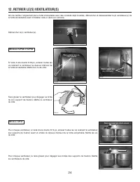
Page 40 - DESMONTAJE DE LOS VENTILADORES
40 12. DESMONTAJE DE LOS VENTILADORES Para facilitar la alineación del grupo de alimentación con los tubos, desenchufe y desmonte los ventiladores del grupo de alimentación antes de instalar la campana. En cada ventilador utilice una llave de tubo de 5/16” para quitar todos los tornillos de montaje ...
Page 41 - INSTALACIÓN DEL GRUPO DE ALIMENTACIÓN; PRECAUCIÓN; Procure no doblar los tubos al instalar el grupo de alimentación.; REINSTALACIÓN DE LOS VENTILADORES
41 13. INSTALACIÓN DEL GRUPO DE ALIMENTACIÓN PRECAUCIÓN Procure no doblar los tubos al instalar el grupo de alimentación. Utilice los tornillos cromados n.° 8 x ½” provistos para instalar el grupo de alimentación en la campana. Empiece por 2 tornillos en las esquinas delanteras; a continuación, util...
Page 42 - REINSTALACIÓN DEL TABLERO INFERIOR
42 14. REINSTALACIÓN DE LOS VENTILADORES ( CONTINUACIÓN ) Enchufe los ventiladores. HE0085 T ODOS LOS MODELOS 15. REINSTALACIÓN DEL TABLERO INFERIOR Levante el tablero inferior y encaje las aletas metálicas del grupo de alimentación en las ranuras del tablero inferior, como se ve en los detalles A y...
Page 43 - REINSTALACIÓN DE LOS FILTROS
43 17. REINSTALACIÓN DE LOS FILTROS PRECAUCIÓN Retire la película protectora de plástico que cubre los filtros antes de instalarlos. Se aconseja instalar primero los filtros laterales y terminar por el o los centrales. 1. Introduzca un extremo del filtro en el canal superior del grupo de alimentació...
Page 44 - blanqueador
44 19. USO Y CUIDADO Placas de los filtros Los filtros deben limpiarse con frecuencia. Utilice una disolución de detergente con agua templada. Lávelos con mayor frecuencia si su tipo de cocina genera más grasa (alimentos fritos o cocina con wok). Retire las placas de los filtros empujándolas hacia l...
Page 46 - GARANTÍA LIMITADA DE UN AÑO
46 21. GARANTÍA GARANTÍA LIMITADA DE UN AÑO Broan-NuTone LLC (“Broan-NuTone”) garantiza al comprador original de sus productos que éstos carecen de defectos en los materiales o de mano de obra por un período de un año a partir de la fecha de compra original. NO EXISTEN OTRAS GARANTÍAS, EXPRESAS O IM...
Page 47 - DIAGRAMA ELÉCTRICO
47 22. DIAGRAMA ELÉCTRICO LÍNEA HILO NEUTRO TIERRA 12 0 V CA B M M AZ R M M AZ R N B CONTROL DE VELOCIDAD TERMOSTATO HS AZ N N AZ N B B B B N N A A L 1 2 AZ AZ AZ AZ CÓDIGO DE COLORES HE0092E A AMARILLOAZ AZULB BLANCOM MARRÓNN NEGROR ROJO INTERRUPTOR DEL VENTILADOR N LÁMPARA LÁMPARA INTERRUPTOR DE L...