Page 2 - TO REDUCE THE RISK OF A RANGE TOP GREASE FIRE:; WARNING
2 TO REDUCE THE RISK OF FIRE, ELECTRIC SHOCK OR INJURY TO PERSONS, OBSERVE THE FOLLOWING: 1. Use this unit only in the manner intended by the manufacturer. If you have questions, contact the manufacturer at the address or telephone number listed in the warranty. 2. Before servicing or cleaning unit,...
Page 3 - - CP55IQ AND CP57IQT POWER PACK SYSTEMS -; POWER PACK; ACR S
3 HL0207 - + ¤ - CP55IQ AND CP57IQT POWER PACK SYSTEMS - M ODEL 634 OR 644 (R OOF CAP ) M ODEL 643 (8” R OUND WALL CAP ) M ODEL 418 (10” R OUND ADJUSTABLE ELBOW ) M ODEL 410 (10” R OUND DUCT — 2 FT . SECTIONS ) 10” R OUND VERTICAL IN - LINE DAMPER ( SUPPLIED WITH DUAL BLOWER POWER PACK ) M ODEL 437 ...
Page 5 - INSTALL DUCTWORK AND ELECTRICAL WIRING; Distances over 30” are at the installer and users discretion.
5 1. INSTALL DUCTWORK AND ELECTRICAL WIRING 1.1 N ON -D UCTED I NSTALLATION (CP55IQ S ERIES POWER PACKS ONLY ) CP55IQ Series power packs may be non-ducted. ANKCP55 non-duct kit must be installed (sold separately). 1.2 D UCTED I NSTALLATION (A LL POWER PACKS ) For a CP57E Series power pack, either an...
Page 6 - PREPARE INSTALLATION; CUSTOM HOOD PREPARATION
6 2. PREPARE INSTALLATION WARNING ! When performing installation, servicing or cleaning the unit, it is recommended to wear safety glasses and gloves. NOTE: Before proceeding to the installation, check the contents of the box. If items are missing or damaged, contact the manufacturer. Make sure that...
Page 7 - REMOVE GREASE DRIP RAIL; Lift grease drip rail to disengage it from the bottom
7 4. MOUNT CUSTOM HOOD INTERNAL FRAMEWORK 5. REMOVE HYBRID BAFFLE FILTERS Remove tape on filters. Remove filters from power pack and set aside. It is recommended to start with the center one(s). HH0102A HD0521 WARNING ! The wood hood must be positively secured to wall studs or other wooden framework...
Page 8 - REMOVE BOTTOM PANEL; Disassemble bottom panel from power pack and set aside.; AND
8 7. REMOVE BOTTOM PANEL Using a Phillips screwdriver, remove both bottom panel retaining screws and set aside. Disassemble bottom panel from power pack and set aside. HO0224 R ETAINING SCREW LOCATIONS HO0120 S IDE VIEW 8. REMOVE KNOCK-OUT OPENING (CP55IQ AND CP57IQT S ERIES ONLY ) From inside the p...
Page 9 - recommended
9 10. INSTALL THE 10” ADAPTER (CP57IQT S ERIES ONLY ) Using 2 no. 8 x 3/8” screws from parts bag, assemble the adapter on the top of the power pack. Seal all joints with metal foil duct tape to eliminate air leaks. NOTE: For a non-ducted installation, do not install the 10” in-line damper. Install 1...
Page 10 - Position the power pack below the installed custom hood.; Insert the house wiring cable through the wire clamp; DO NOT FORGET TO CONNECT THE GROUND; Reinstall wiring box cover.; ERIES; INSTALL POWER PACK; CAUTION; Take care not to kink ducting when installing the power pack.; to install the power pack in its custom hood.
10 13. CONNECT WIRING ( ALL BLOWERS ) Position the power pack below the installed custom hood. WARNING ! Risk of electric shock. Electrical wiring must be done by qualified personnel in accordance with all applicable codes and standards. Before connecting wires, switch power off at service panel and...
Page 11 - REINSTALL BOTTOM PANEL; and; REINSTALL GREASE DRIP RAIL; Insert one end of grease rail in power pack side (; PERFORM THE EXTERNAL BLOWER CONNECTIONS (CP57E S; plate to the 2-prong plug inside the power pack (; Do not plug the two cords together.
11 16. REINSTALL BOTTOM PANEL Lift the bottom panel and engage the power pack metal tabs in bottom panel slots, as shown in details A and B below. Secure the bottom panel to the power pack using its screws previously removed in step 7. HO0224 R ETAINING SCREW LOCATIONS HO0121 A B S IDE VIEW 17. REIN...
Page 12 - REINSTALL HYBRID BAFFLE FILTERS
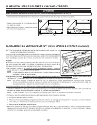
12 19. CALIBRATE IQ BLOWER SYSTEM™ (CP55IQ & CP57IQT SERIES ONLY ) NOTE: Calibration is for ducted installations only. Do not calibrate non-ducted installations. After the power pack is installed and wired, engage the calibration process (our Guaranteed Performance System Technology to ensure fu...
Page 13 - Avoid when choosing a detergent:; Do not touch lamps during or soon after operation. Burns may occur.
13 21. USE AND CARE Hybrid Baffle Filters The hybrid baffle filters should be cleaned frequently. Use a warm detergent solution. Wash more often if your cooking style generates greater grease — like frying foods or wok cooking. Remove hybrid baffle filters by pushing them towards the back of power p...
Page 14 - HEAT SENTRYTM; button LED will flash. The blower will remain
14 22. OPERATION Always turn your blower on before you begin cooking to establish an airflow in the kitchen. Let the blower run for a few minutes to clear the air after you turn off the range. HC0016 S PEED 1 2 3 4 B A C D E A. B LOWER DELAY - OFF BUTTON : When blower is on, press the delay-off butt...
Page 15 - BLD C; A C
15 23. WIRING DIAGRAMS 5 2 3 4 J1 1 5 2 3 4 J1 1 3 J7 2 3 J7 2 1 3 2 1 Q1Q1 K4 K3 K2 K1 + - ~ ~ + - ~ ~ + - ~ ~ + - ~ ~ M OT OR L OW M ED L OW M ED H IGH H IGH L AM P L OW V AC R EF CO NT RO L B O A R D 5 2 3 4 1 3 2 1 + - ~ ~ + - ~ ~ BL U BLD C POW ER BOARD BL DC M C ALIBRATION S WITCH WH T OR G BL...
Page 16 - CONT; Li; BLDC; EF
16 23. WIRING DIAGRAMS ( CONT ' D ) BL U WH T OR G BL K Li n e N eut ra l G rou nd 120 V A C BL K BL K T1T1 WH T RE D WH T WH T RE D WH T YE L Speed 4 Speed 3 Speed 2 Speed 1 M A IN S W IT C H Ne u tr a l YE L WH T WH T BL K BL K BL K BL K BLDC POW ER BOARD BLDC POW ER BOARD M M M M BL K BL K WHT WH...
Page 17 - Best CP57E Series
17 23. WIRING DIAGRAMS ( CONT ' D ) BLK YE L M BRN GR Y RE D BL K OR G WH T BL U BLK BLK BLK ORG WHT BLU WHT ORG WHT BLU 1 2 2 1 WHT BLK BL K WH T GR N BL K WH T WH T BLK WHT RO UG H -I N P L AT E WH T BL K WH T BLK GR N T2 BLK 120 ORG 120 BLU 88 PPL 60 PN K 4 5 YEL 10 WHT 0 WHT 0 BLK ORG WHT BLU WH...
Page 18 - Best CP55IQ & CP57IQT Series; BLDC B
18 24. SERVICE PARTS Best CP55IQ & CP57IQT Series HL0477 1 2 3 4 6 5 7 9 10 13 11 12 14 8 R EPLACEMENT P ARTS AND R EPAIRS In order to ensure your unit remains in good working condition, you must use Broan-NuTone genuine replacement parts only. Broan-NuTone genuine replacement parts are speciall...
Page 19 - PCB
19 24. SERVICE PARTS ( CONT ' D ) Best CP57E Series HL0478 1 3 4 7 8 9 10 2 6 5 R EPLACEMENT P ARTS AND R EPAIRS In order to ensure your unit remains in good working condition, you must use Broan-NuTone genuine replacement parts only. Broan-NuTone genuine replacement parts are specially designed for...
Page 21 - CONÇUES POUR USAGE DOMESTIQUE SEULEMENT; INSTALLATEUR : LAISSER CE GUIDE AU PROPRIÉTAIRE.; LIRE ET CONSERVER CES DIRECTIVES; GUIDE D’INSTALLATION
SÉRIES CP55IQ, CP57IQT ET CP57E CONÇUES POUR USAGE DOMESTIQUE SEULEMENT INSTALLATEUR : LAISSER CE GUIDE AU PROPRIÉTAIRE. PROPRIÉTAIRE : DIRECTIVES D’UTILISATION ET D’ENTRETIEN EN PAGES 33 ET 34. LIRE ET CONSERVER CES DIRECTIVES BEST; Hartford, Wisconsin www.BestRangeHoods.com 800 558-1711BEST; Drumm...
Page 22 - AFIN DE RÉDUIRE LES RISQUES DE FEU DE CUISINIÈRE :; Kitchen Fire Safety Tips; AVERTISSEMENT
22 AFIN DE RÉDUIRE LES RISQUES D’INCENDIE, D’ÉLECTROCUTION OU DE BLESSURES CORPORELLES, SUIVEZ LES DIRECTIVES SUIVANTES : 1. N’utilisez cet appareil que de la façon prévue par le manufacturier. Si vous avez des questions, contactez le manufacturier à l’adresse ou au numéro de téléphone indiqués dans...
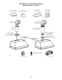
Page 24 - HOTTE ENCASTRABLE
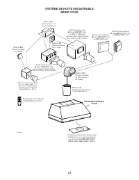
24 HL0208 - + ¤ - SYSTÈME DE HOTTE ENCASTRABLE - SÉRIE CP57E M ODÈLE 441 (C APUCHON MURAL 10 PO ROND ) M ODÈLE 437 (C APUCHON DE TOIT À HAUT RENDEMENT ) V ENTILATEUR EN LIGNE M ODÈLE ILB9 (800 PCM ) OU ILB11 (1100 PCM ) ( INCLUANT DEUX TRANSITIONS DE 8 PO X 12 PO À 10 PO ROND ) M ODÈLE 418 (C OUDE A...
Page 25 - INSTALLER LES CONDUITS ET LE CÂBLAGE ÉLECTRIQUE; de 8 po et d'une longueur minimale de 12 po pour un conduit de 10 po.
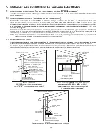
25 HH0115F VENTILATEUR EXTÉRIEUR VENTILATEUR EXTÉRIEUR HOTTE ENCASTRABLE CONDUITS RONDS DE 10 PO DE 24 PO À 30 POAU-DESSUS DE LASURFACE DE CUISSON COUDE ROND DE 10 PO I NSTALLATION TYPE CP57E AVEC VENTILATEUR EN LIGNE MODÈLE ILB3, ILB6, ILB9 OU ILB11 ( L ’ EMPLACEMENT DU VENTILATEUR EST ILLUSTRÉ À T...
Page 26 - PRÉPARER L’INSTALLATION; PRÉPARATION DE L’ARMOIRE POUR HOTTE
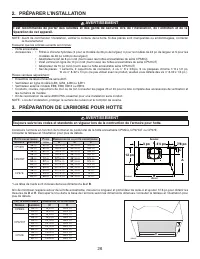
26 2. PRÉPARER L’INSTALLATION AVERTISSEMENT ! Il est recommandé de porter des lunettes et des gants de sécurité lors de l’installation, de l’entretien et de la réparation de cet appareil. A B C 7/8 po 4½ po HD0296F C L 12 po 3 po A RRIÈRE A VANT 3. PRÉPARATION DE L’ARMOIRE POUR HOTTE AVERTISSEMENT !...
Page 27 - RETIRER LA GOUTTIÈRE; Glisser la gouttière complètement vers la gauche ou
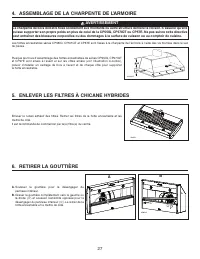
27 4. ASSEMBLAGE DE LA CHARPENTE DE L’ARMOIRE 5. ENLEVER LES FILTRES À CHICANE HYBRIDES Enlever le ruban adhésif des filtres. Retirer les filtres de la hotte encastrable et les mettre de côté. Il est recommandé de commencer par le(s) filtre(s) du centre. HH0102F AVERTISSEMENT ! La charpente de bois ...
Page 28 - ÉRIE; RETIRER LE PANNEAU INFÉRIEUR; ÉRIES
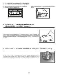
28 HJ0016 E MPLACEMENT DES VIS D ’ ASSEMBLAGE Par l’intérieur de la hotte encastrable, retirer le couvercle de la boîte de jonction en dévissant les 2 vis de retenue et les mettre de côté. Défoncer l’ouverture préamorcée pour le fil d’alimentation électrique située sur le dessus de la hotte encastra...
Page 29 - recommandé
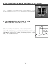
29 10. INSTALLER L’ADAPTATEUR DE 10 PO (S ÉRIE CP57IQT SEULEMENT ) À l’aide de 2 vis n° 8 x 3/8 po fournies dans le sac de pièces, assembler l’adaptateur sur le dessus de la hotte encastrable. Sceller les joints avec du ruban adhésif de métal pour éliminer les fuites d’air. NOTE : Pour une installat...
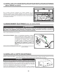
Page 30 - Placer la hotte encastrable sous son armoire.; VENTILATEURS INTERNES :; Passer le fil d’alimentation électrique à travers le; NE; Remettre en place le couvercle de la boîte; VENTILATEURS EXTÉRIEURS OU EN LIGNE; : Voir les directives incluses avec ce; INSTALLER LA PLAQUE VENTILATEUR POUR VENTILATEURS EXTERNES; INSTALLER LA HOTTE ENCASTRABLE; ATTENTION
30 13. BRANCHEMENT ÉLECTRIQUE ( TOUS LES VENTILATEURS ) Placer la hotte encastrable sous son armoire. AVERTISSEMENT ! Risque d’électrocution. Le raccordement électrique doit être effectué par du personnel qualifié conformément aux codes et aux standards. Avant d’effectuer le branchement, coupez l’al...
Page 31 - REMETTRE LA GOUTTIÈRE EN PLACE; REMETTRE EN PLACE LE PANNEAU INFÉRIEUR
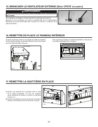
31 Fixer le panneau inférieur à la hotte encastrable à l’aide de ses vis retirées précédemment à l’étape 7. HO0224 E MPLACEMENT DES VIS DE RETENUE 17. REMETTRE LA GOUTTIÈRE EN PLACE 15. BRANCHER LE VENTILATEUR EXTERNE (S ÉRIE CP57E SEULEMENT ) Pour installer le ventilateur, voir les instructions com...
Page 32 - CALIBRER LE VENTILATEUR IQ; SÉRIES; RÉINSTALLER LES FILTRES À CHICANE HYBRIDES
32 Il est recommandé d’installer d’abord les filtres situés aux extrémités et de terminer par le(s) filtre(s) du centre. 1. Insérer une extrémité du filtre hybride dans le rail avant de la hotte. 2. Lever l’autre bout du filtre à l’intérieur de la hotte et l’insérer dans la gouttière. 1 HD0526 2 19....
Page 33 - Nettoyage de la hotte encastrable
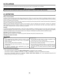
33 21. ENTRETIEN Filtres à chicane hybrides Les filtres à chicane hybrides doivent être nettoyés fréquemment. Utiliser une solution d’eau chaude et de détergent. Nettoyer les filtres à chicane souvent si vos habitudes de cuisson génèrent beaucoup de graisse, comme la friture ou les aliments sautés a...
Page 34 - HEAT SENTRY; la DEL du bouton de la vitesse
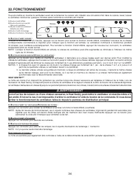
34 A. B OUTON D ’ ARRÊT DIFFÉRÉ : Lorsque le ventilateur est en marche, appuyer sur ce bouton pour activer la fonction d’arrêt différé. L’indicateur lumineux de la vitesse correspondante commencera à clignoter pour indiquer que la fonction est activée. Le ventilateur continuera à fonctionner pendant...
Page 35 - SCHÉMAS ÉLECTRIQUES; Série CP55IQ de Best (ventilateur interne); CA
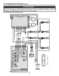
35 23. SCHÉMAS ÉLECTRIQUES AVERTISSEMENT ! Risque d’électrocution. Le raccordement électrique doit être effectué par du personnel qualifié conformément aux codes et aux standards. Avant d’effectuer le branchement, coupez l’alimentation électrique au panneau de distribution et verrouillez-le pour évi...
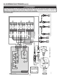
Page 36 - ign; Série CP57IQT de Best (ventilateur double); SUITE
36 BL E BLA O N N N T1T1 BLA R BLA BLA R BLA J J BLA BLA N N N N BLDC POW ER BOARD BLDC POW ER BOARD M M M M N N BLA M M BLA R BLA BLA R R BLA BLA R M ODÈLE DE HOTTE À 4 LAMPES DEL 3 2 1 3 2 1 21 21 212 1 21 21 212 1 R É F : 70120 RÉV. B 5 2 3 4 J1 1 5 2 3 4 1 3 J7 2 3 J7 2 1 3 2 1 Q1Q1 K4K4 K3K3 K2...
Page 37 - Série CP57E de Best
37 N J M BR G RO U N O BL E N N N O BLE O BLE 1 2 2 1 BLA N N BLA V N BLA BLA N BLA RO UG H -I N P L AT E BLA N N V T2 N 120 O 120 BLE 88 P 60 ROS 4 5 J 10 BLA 0 BLA 0 N O BLE T3 O 120 BLE 88 P 6 0 ROS 45 J 10 BLA 0 BLA 0 N 120 T1 N 120 O 120 BLE 88 P 60 ROS 45 J 10 BLA 0 BLA 0 T1 N Fusible 8 A 21 2...
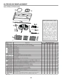
Page 38 - N° P; CC; PIÈCES DE REMPLACEMENT; Séries CP55IQ et CP57IQT de Best
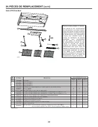
38 P IÈCES DE REMPLACEMENT ET SERVICE Pour assurer le bon fonctionnement de votre appareil, vous devez toujours utiliser des pièces d’origine provenant de Broan-NuTone. Les pièces d’origine de Broan-NuTone sont spécialement conçues pour satisfaire toutes les normes de certification de sécurité appli...
Page 40 - dispositions de la garantie limitée restent valides.; Best
40 25. GARANTIE GARANTIE LIMITÉE DE 5 ANS SUR LES PRODUITS BEST MD Période de garantie et exclusions : Broan-NuTone LLC (l’« entreprise ») garantit au consommateur qui achète son produit (« vous ») que le produit (le « produit ») restera exempt de défauts importants dans ses composants ou sa fabrica...
Page 41 - EXCLUSIVAMENTE PARA COCINAS DOMÉSTICAS; INSTALADOR: ENTREGUE ESTE MANUAL AL PROPIETARIO DE LA CASA.; LEA ESTAS INSTRUCCIONES Y GUÁRDELAS; INSTRUCCIONES DE INSTALACIÓN
EXCLUSIVAMENTE PARA COCINAS DOMÉSTICAS INSTALADOR: ENTREGUE ESTE MANUAL AL PROPIETARIO DE LA CASA. PROPIETARIO: INFORMACIÓN SOBRE UTILIZACIÓN Y CUIDADO EN LAS PÁGINAS 53 Y 54. LEA ESTAS INSTRUCCIONES Y GUÁRDELAS ! ! SERIES CP55IQ, CP57IQT Y CP57E INSTRUCCIONES DE INSTALACIÓN BEST; Hartford, Wisconsi...
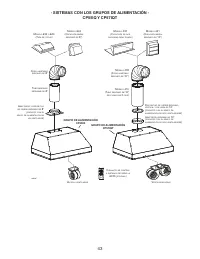
Page 43 - - SISTEMAS CON LOS GRUPOS DE ALIMENTACIÓN -; GRUPO DE ALIMENTACIÓN
43 HL0207 - + ¤ - SISTEMAS CON LOS GRUPOS DE ALIMENTACIÓN - CP55IQ Y CP57IQT M ODELO 634 O 644 (T APA DE TECHO ) M ODELO 643 (C APUCHÓN MURAL REDONDO DE 8”) M ODELO 418 (C ODO AJUSTABLE REDONDO DE 10”) M ODELO 410 (T UBO REDONDO DE 10”, SECCIONES DE 2 PIES ) D ISPOSITIVO DE CIERRE REDONDO , VERTICAL...
Page 45 - INSTALACIÓN DE LOS TUBOS Y DE LAS CONEXIONES ELÉCTRICAS
45 1. INSTALACIÓN DE LOS TUBOS Y DE LAS CONEXIONES ELÉCTRICAS 1.1 S IN TUBOS ( SÓLO GRUPOS DE ALIMENTACIÓN CP55IQ) Los grupos de alimentación de la serie CP55IQ pueden usarse sin tubos. Para ello, debe instalarse el conjunto sin tubos ANKCP55, que se vende aparte. 1.2 I NSTALACIÓN CON TUBOS ( TODOS ...
Page 46 - PREPARACIÓN DE LA INSTALACIÓN; ADVERTENCIA; PREPARACIÓN DE LA CAMPANA A MEDIDA; comprenden las cabezas de los remaches.
46 NOTA: Antes de comenzar la instalación, verificar el contenido de la caja. Si alguna pieza falta o está dañada, póngase en contacto con el fabricante. Compruebe que el conjunto para la instalación contiene los elementos siguientes: - Grupo de alimentación- Accesorios: • Filtros híbridos (3 para e...
Page 47 - Se aconseja empezar por el filtro o filtros centrales.; DESMONTAJE DEL RIEL DE VERTIDO DE LA GRASA; Deslice el riel completamente a la izquierda o a la
47 4. MONTAJE DEL ARMAZÓN INTERNO DE LA CAMPANA A MEDIDA 5. DESMONTAJE DE LOS FILTROS HÍBRIDOS Retire la cinta de los filtros. Saque los filtros del grupo de alimentación y póngalos aparte. Se aconseja empezar por el filtro o filtros centrales. HH0102A ADVERTENCIA ! La campana de madera ha de estar ...
Page 48 - DESMONTAJE DEL TABLERO INFERIOR
48 HJ0016 U BICACIÓN DE LOS TOR NILL OS DE INSTALACIÓN 8. DESMONTAJE DE LA ABERTURA DESMONTABLE (S ERIES CP55IQ Y CP57IQT ÚNICAMENTE ) Desde la parte interior del grupo de alimentación, quite la tapa de las conexiones retirando ambos tornillos de retención (guárdelos). Perfore el orificio desmontabl...
Page 49 - aconsejado
49 10. INSTALACIÓN DEL ADAPTADOR DE 10” (S ERIE CP57IQT ÚNICAMENTE ) Utilice 2 tornillos n.° 8 x 3/8” de la bolsa de piezas para instalar el adaptador en la parte superior del grupo de alimentación. Precinte todas las juntas con cinta adhesiva metálica para tubos para que no se escape el aire. NOTA:...
Page 50 - Ponga el grupo de alimentación debajo de la campana instalada.; VENTILADORES INTERIORES:; Introduzca el cable de conexión doméstico a; NO OLVIDE CONECTAR LA TIERRA; instalar la tapa de conexiones.; VENTILADORES EXTERIOR O EN LÍNEA:; ERIE; INSTALACIÓN DEL GRUPO DE ALIMENTACIÓN; PRECAUCIÓN; Procure no doblar los tubos al instalar el grupo de alimentación.
50 13. CONEXIÓN DEL CABLEADO (T ODOS LOS VENTILADORES ) Ponga el grupo de alimentación debajo de la campana instalada. ADVERTENCIA ! Riesgo de choque eléctrico. La conexión eléctrica debe hacerla personal competente con arreglo a los códigos y normas en vigor. Antes de conectar los hilos, corte la a...
Page 51 - Introduzca un extremo del riel en el lado (; INSTALACIÓN DE LAS CONEXIONES DE LOS VENTILADORES EXTERIORES; No enchufe un cable en el otro.
51 16. REINSTALACIÓN DEL TABLERO INFERIOR Levante el tablero inferior y encaje las aletas metálicas del grupo de alimentación en las ranuras del tablero inferior, como se ve en los detalles A y B de abajo. Sujete el tablero inferior al grupo de alimentación con los tornillos que quitó en la etapa 7....
Page 52 - REINSTALACIÓN DE LOS FILTROS HÍBRIDOS; Introduzca un extremo del filtro híbrido en el; Calibración exitosa. Presione el botón para apagar la luz LED.
52 18. REINSTALACIÓN DE LOS FILTROS HÍBRIDOS PRECAUCIÓN Retire la película protectora de plástico que cubre los filtros híbridos antes de instalarlos. 1 HD0526 2 Se aconseja instalar primero los filtros laterales y terminar por el o los centrales. 1. Introduzca un extremo del filtro híbrido en el ca...
Page 53 - Limpieza del grupo de alimentación; blanqueador; Filtros híbridos
53 Limpieza del grupo de alimentación Limpieza del acero inoxidable: Al escoger un detergente, evite: - Los limpiadores que contienen blanqueador (lejía), ya que dañarán el acero inoxidable. - Los productos que contengan cloruro, fluoruro, yoduro y bromuro , ya que deterioran las superficies rápidam...
Page 54 - la LED del botón de la
54 22. FUNCIONAMIENTO Ponga en marcha siempre el ventilador antes de empezar a cocinar para generar una corriente de aire en la cocina. Deje en marcha el ventilador durante unos minutos para renovar el aire una vez que haya apagado la cocina. HC0016 V ELOCIDAD 1 2 3 4 B A C D E A. I NTERRUPTOR DE RE...
Page 55 - DIAGRAMAS ELÉCTRICOS; Lí; Serie CP55IQ de Best (un solo ventilador)
55 23. DIAGRAMAS ELÉCTRICOS ADVERTENCIA ! Riesgo de choque eléctrico. La conexión eléctrica debe hacerla personal competente con arreglo a los códigos y normas en vigor. Antes de conectar los hilos, corte la alimentación en el tablero de servicio y bloquee los medios de desconexión para impedir que ...
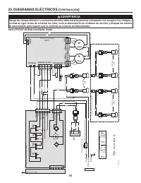
Page 56 - CONTINUACIÓN
56 23. DIAGRAMAS ELÉCTRICOS ( CONTINUACIÓN ) ADVERTENCIA ! Riesgo de choque eléctrico. La conexión eléctrica debe hacerla personal competente con arreglo a los códigos y normas en vigor. Antes de conectar los hilos, corte la alimentación en el tablero de servicio y bloquee los medios de desconexión ...
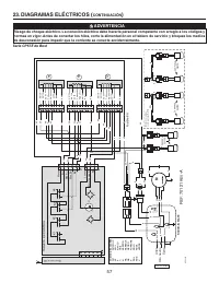
Page 57 - Fusible 8 A; Serie CP57E de Best
57 NE AM M M G RO J NE NA B AZ NE NE NE NA B AZ B NA B AZ 1 2 2 1 B NE NE B V NE B B NE B RO UG H -I N P L AT E B NE B NE V T2 NE 120 NA 120 AZ 88 P 60 ROS 4 5 AM 10 B 0 B 0 NE NA B AZ B B T3 NA 120 AZ 88 P 6 0 ROS 45 AM 10 B 0 B 0 NE 120 T1 NE 120 NA 120 AZ 88 P 60 ROS 45 AM 1 0 B 0 B 0 T1 NE Fusib...
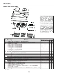
Page 58 - Series CP55IQ y CP57IQT de Best
58 S USTITUCIÓN DE PIEZAS Y REPARACIÓN Para que la unidad se conserve en buen estado, debe usar repuestos genuinos de Broan-NuTone únicamente. Estas piezas se han diseñado especialmente para cada unidad y se han fabricado conforme a las normas de certificación aplicables y un elevado nivel de seguri...


 Best CC65I28SB
User Manual
Best CC65I28SB
User Manual
 Best CP34I429SB
User Manual
Best CP34I429SB
User Manual
 Best CP35I309SB
User Manual
Best CP35I309SB
User Manual
 Best CPD9M363SB
User Manual
Best CPD9M363SB
User Manual
 Best CPDI362SB
User Manual
Best CPDI362SB
User Manual
 Best HBC143ESS
User Manual
Best HBC143ESS
User Manual