Page 2 - READ AND SAVE THESE INSTRUCTIONS; fl; fl; INTENDED FOR DOMESTIC COOKING ONLY
- 2 - READ AND SAVE THESE INSTRUCTIONS WARNING TO REDUCE THE RISK OF FIRE, ELECTRIC SHOCK, OR INJURY TO PERSONS, OBSERVE THE FOLLOWING: 1. Use this unit only in the manner intended by the manufacturer. If you have questions, contact the manufacturer at the address or telephone number listed in the w...
Page 3 - CAUTION
- 3 - ! CAUTION 1. For indoor use only.2. To reduce risk of fi re and to properly exhaust air, be sure to duct air outside. Do not vent exhaust air into spaces within walls or ceilings or into attics, crawl spaces, or garages. 3. Take care when using cleaning agents or detergents.4. Avoid using food...
Page 4 - PREPARE THE HOOD; Unpack hood and check contents.
- 4 - PREPARE THE HOOD Unpack hood and check contents. 1 - Hood1 - Hardware Bag (B08084041) containing: 4 - Mounting Screws (4,2 x 20 mm Pan Head)1 - Parts Bag (B08084042) containing: 1 - Junction Box 1 - Junction Box Cover 2 - Cover Screws (3,9 x 6 Flat Head) 4 - Washer 2 - Mounting Screws (3,9 x 9...
Page 5 - INSTALL THE DUCTWORK; NOTE: To reduce the risk of; INSTALL JUNCTION BOXE
- 5 - INSTALL THE DUCTWORK NOTE: To reduce the risk of fi re, use only metal ductwork. 1. Decide where to install the duct.2. A straight, short duct will allow the hood to perform most e ffi ciently. 3. Long duct, elbows, and transitions will re- duce the performance of the hood. Use as few of them as...
Page 6 - INSTALL THE HOOD; WIRING; CONNECT DUCTWORK
- 6 - INSTALL THE HOOD 1. Cut a hole in the bottom of the cabinet. See Fig.5 2. To install the hood, adjust the position of the clasping side spring by turning the screws, according to the thickness of the cabinet to which it is going to be anchored. See Fig.6 3. Insert the hood in the cabinet and l...
Page 7 - MAINTENANCE; Grease Filters; grease; Hood Cleaning; DO NOT
- 7 - MAINTENANCE Grease Filters The grease fi lter/s should be cleaned frequent- ly. Use a warm detergent solution. Grease fi lters are dishwasher safe. To take o ff the grease fi lter/s fi rst open the closure panel pulling downwards. See Fig.10 To take o ff the grease fi lter/s: at the handle, push...
Page 8 - OPERATION; HEAT SENTRYTM
- 8 - OPERATION The hood is operated using the (5) push buttons located on the front edge of the hood. The Light O ff switch turns the lights o ff and on. The Light Intensity switch increases and decreases the lighting level. The Blower O ff /Speed switch turns the blower o ff and changes blower speed t...
Page 9 - HALOGEN SPOTLIGHT; This range hood requires two halogen; WARNING: Always switch o; Open the cover by prying from the; Do not
- 9 - HALOGEN SPOTLIGHT This range hood requires two halogen bulbs (Type T3, 12Volt, 20Watt Max, G-4 Base). WARNING: Always switch o ff the electricity supply before carrying out any operations on the appliance. 1. Open the cover by prying from the proper slots. See Fig. 12. 2. Remove the bulb by pul...
Page 11 - SERVICE PARTS
- 11 - SERVICE PARTS B003100148B003100147 B02011013 B08087694B08087527B02300804B08093332 BE3350233BE3334252 B03295008 BE3405682BE3405683 B02011422 B02300806 B02011376 B02301058B02320371B08084041 B080814410 B06102757 B06102773B06102756 B080814051B080810849 B06002309U FRAME - ONLY FOR P195P1M52 MODEL ...
Page 12 - LISEZ ET CONSERVEZ CES INSTRUCTIONS; POUR USAGE DOMESTIQUE SEULEMENT; RELLES, SUIVEZ LES INSTRUCTIONS SUIVANTES :
- 12 - LISEZ ET CONSERVEZ CES INSTRUCTIONS POUR USAGE DOMESTIQUE SEULEMENT ! ! AVERTISSEMENT AFIN DE RÉDUIRE LES RISQUES D’INCENDIE, D’ÉLECTROCUTION OU DE BLESSURES CORPO- RELLES, SUIVEZ LES INSTRUCTIONS SUIVANTES : 1. N’utilisez cet appareil que de la façon prévue par le fabricant. Pour d’autres re...
Page 13 - AVERTISSEMENT; ATTENTION
- 13 - AVERTISSEMENT AFIN D’ÉVITER TOUS RISQUES DE BLESSURE LORS D’UN FEU DE CUISINIÈRE, OBSERVEZ LES INSTRUCTIONS SUIVANTES* :1. ÉTOUFFEZ LES FLAMMES à l’aide d’un couvercle hermétique, une plaque à biscuits ou un plateau en métal, puis éteignez le brûleur. ATTENTION DE NE PAS VOUS BRÛLER. Si les f...
Page 14 - PRÉPARATION DE LA HOTTE; Retirer la hotte de l’emballage, puis véri
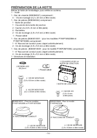
- 14 - PRÉPARATION DE LA HOTTE Retirer la hotte de l’emballage, puis véri fi er le contenu. 1 - Hotte1 - Sac de visserie (B08084041) comprenant : 4 - Vis de montage (4,2 x 20 mm à tête ronde) 1 - Sac de pièces (B08084042) comprenant: 1 - Boîte de jonction1 - Couvercle de la boîte de jonction2 - Cach...
Page 15 - POSE DU CONDUIT; NOTE: Pour réduire le risque d’incendie,
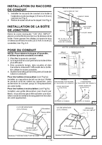
- 15 - POSE DU CONDUIT NOTE: Pour réduire le risque d’incendie, n’utiliser que des conduits en métal. 1. Plani fi er la pose du conduit. 2. Un tracé droit et court permet à la hotte d’être plus e ffi cace. 3. Des conduits longs, des coudes et des transitions réduisent l’e ffi cacité de la hotte. En util...
Page 16 - INSTALLATION DE LA HOTTE; INSTALLATION ÉLECTRIQUE
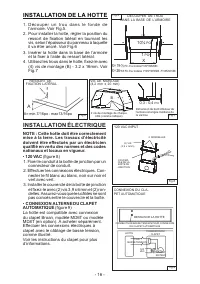
- 16 - A INSTALLATION DE LA HOTTE 1. D é c o u p e r u n t r o u d a n s l e f o n d e d e l’armoire. Voir Fig.5. 2. Pour installer la hotte, régler la position du ressort de fi xation latéral en tournant les vis, selon l’épaisseur du panneau à laquelle il va être ancré. Voir Fig.6 3. Insérer la hot...
Page 17 - ENTRETIEN; Filtres à graisses; ltres à graisses; Nettoyage de votre hotte; KIT D’INSTALLATION DE RECIRCULATION; NE PAS LAISSER; RACCORDEMENT DU CONDUIT
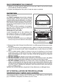
- 17 - ENTRETIEN Filtres à graisses Les fi ltres à graisses doivent être nettoyés fréquemment. Utiliser une solution d’eau chaude additionnée de détergent. Les fi ltres à graisses peuvent être lavés au lave-vaisselle. Pour enlever le fi ltres à graisses d’abord ouvrir le panneau de fermeture en tira...
Page 18 - FONCTIONNEMENT; DÉTECTEUR DE CHALEUR; il actionnera le ventilateur à haute vitesse.
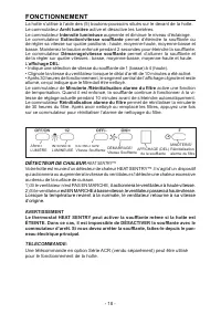
- 18 - ARRÊT LUMIÈRE INTENSITÉLUMINEUSE EXTINCTION/Vitesse Sou ffl ante AFFICHAGE (DEL) de la sou ffl ante DÉMARRAGE/Vitesse Sou ffl ante FONCTIONNEMENT La hotte s’utilise à l’aide des (5) boutons-poussoirs situés sur le devant de la hotte.Le commutateur Arrêt lumière active et désactive les lumières. Le ...
Page 19 - AMPOULE HALOGÈNE; C e t t e h o t t e r e q u i e r t d e u x a m p o u l e s; AVERTISSEMENT: Toujours; Ouvrez le couvercle en faisant levier; TOURNE PAS
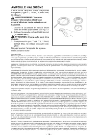
- 19 - AMPOULE HALOGÈNE C e t t e h o t t e r e q u i e r t d e u x a m p o u l e s halogènes (Type T3, 12Volt, 20Watt Max, G-4 Base). AVERTISSEMENT: Toujours couper l’alimentation électrique avant d’e ff ectuer toute opération sur l’appareil. 1. Ouvrez le couvercle en faisant levier dans les fentes ...
Page 21 - LISTE DES PIÈCES DE RECHANGE
- 21 - LISTE DES PIÈCES DE RECHANGE B003100148B003100147 B02011013 B08087694B08087527B02300804B08093332 BE3350233BE3334252 B03295008 BE3405682BE3405683 B02011422 B02300806 B02011376 B02301058B02320371B08084041 B080814410 B06102757 B06102773B06102756 B080814051B080810849 B06002309U GRILLE - SEULEMENT...
Page 22 - LEA Y CONSERVE ESTAS INSTRUCCIONES; ATENTAMENTE LAS SIGUIENTES NORMAS:; ADVERTENCIA; INDICADO PARA EL USO EN COCINAS DOMESTICAS
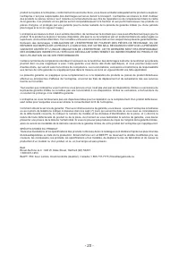
- 22 - LEA Y CONSERVE ESTAS INSTRUCCIONES ADVERTENCIA PARA EVITAR EL RIESGO DE INCENDIO, CORTOCIRCUITO O DAÑO PARA LAS PERSONAS, OBSERVE ATENTAMENTE LAS SIGUIENTES NORMAS: 1. Use esta unidad solamente de la manera indicada por el fabricante; si tiene dudas, póngase en contacto con éste a la direcció...
Page 24 - PREPARE LA CAMPANA; Sacar la campana de l’embalaje y controlar el contenido.
- 24 - PREPARE LA CAMPANA Sacar la campana de l’embalaje y controlar el contenido. 1 - Campana1 - Bolsita (B08084041) con: 4 - Tornillos de montaje (4,2 x 20mm cabeza redonda)1 - Parts Bag (B08084042) con: 1 - Caja de conexiónes 1 - Tapa de la caja 2 - Tornillo de la tapa (3,9 x 6 cabeza plana) 4 - ...
Page 26 - INSTALACION ELECTRICA; INSTALACION DE LA CAMPANA
- 26 - A= min 7/16”-max 13/16” ENGANCHE LATERALE A TORNILLOS DE MONTAJE (4.2x20mm) Fig.5 Fig.6 Fig.7 INSTALACION ELECTRICA Nota: Este tipo de campana tiene que ser conectada a tierra cuidadosamente. La uni- dad debe instalarla un técnico electricista siguiendo las normas nacionales y locales. 120 VC...
Page 27 - MANTENIMIENTO; f i l t r o s a n t i - g r a s a; Limpieza de la campana; No deje; ENTUBADO DE CANALIZACION; tubo de metal
- 27 - CLOSURE PANEL GREASE FILTER/S Fig.10 Fig.11 INSTALACION DEL KIT RECIRCULACION(Opción únicamente sin conducto) Compre un juego de fi ltros Modelo AFCP195P52 por el modelo P195P1M52 o AFCP195P70 por los modelos P195PM70 a su proveedor. Sostituya los fi ltros cada 3 meses. MANTENIMIENTO Filtros ...
Page 28 - FUNCIONAMIENTO
- 28 - FUNCIONAMIENTO La campana se opera mediante los 5 botones pulsadores que se encuentran en el frontal de la campana. El interruptor de apagado de la luz se enciende y apaga las luces. El interruptor de intensidad de la luz aumenta y disminuye el nivel de iluminación. El interruptor de apagado/...
Page 29 - LAMPARAS HALOGENAS; AT E N C I Ó N: antes de proceder; Para cambiar las lámparas:; NO LA GIRE; Sustituir con lámparas del mismo tipo
- 29 - ! Fig.12 LAMPARAS HALOGENAS Este tipo de campana necesita dos (2) lám- paras halógenas (Tipo T3, 12Volt, 20Watt max, G-4 Base). AT E N C I Ó N: antes de proceder a cualquier operación, es necesario desconectar el aparato. Para cambiar las lámparas: 1. Abra la tapa haciendo palanca sobre las h...
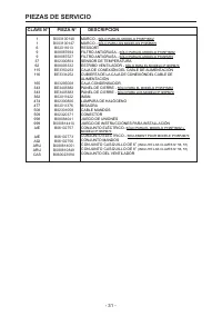
Page 31 - PIEZAS DE SERVICIO; CLAVE N° PIEZA N° DESCRIPCIÓN
- 31 - PIEZAS DE SERVICIO B003100148B003100147 B02011013 B08087694B08087527B02300804B08093332 BE3350233BE3334252 B03295008 BE3405682BE3405683 B02011422 B02300806 B02011376 B02301058B02320371B08084041 B080814410 B06102757 B06102773B06102756 B080814051B080810849 B06002309U MARCO - SÓLO PARA EL MODELO ...
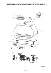
Page 32 - SERVICE PARTS - PIÈCES DE RECHANGE - PIEZAS DE SERVICIO
- 32 - SERVICE PARTS - PIÈCES DE RECHANGE - PIEZAS DE SERVICIO 04308930/1 99045018F