Page 2 - Contact Information; ASRock Incorporation; Scan the QR code to view more manuals and documents.
Contact Information If you need to contact ASRock or want to know more about ASRock, you’re welcome to visit ASRock’s website at http://www.asrock.com; or you may contact your dealer for further information. For technical questions, please submit a support request form at https://event.asrock.com/ts...
Page 3 - Contents; Chapter 1 Introduction
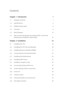
Contents Chapter 1 Introduction 1 1.1 Package Contents 1 1.2 Specifications 2 1.3 Motherboard Layout 6 1.4 I/O Panel 9 1.5 Block Diagram 12 1.6 802.11ax Wi-Fi 6E Module and ASRock WiFi 2.4/5/6 GHz Antennas (For B760M Pro RS/D4 WiFi) 13 Chapter 2 Installation 15 2.1 Installing the CPU 16 2.2 Installi...
Page 5 - Package Contents
1 B760M Pro RS/D4 WiFiB760M Pro RS/D4 Chapter 1 Introduction Thank you for purchasing ASRock B760M Pro RS/D4 WiFi / B760M Pro RS/D4 motherboard, a reliable motherboard produced under ASRock’s consistently stringent quality control. It delivers excellent performance with robust design conforming to A...
Page 6 - Chipset
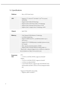
2 1.2 Specifications Platform • Micro ATX Form Factor CPU • Supports 13 th Gen & 12 th Gen Intel® Core TM Processors (LGA1700) • Supports Intel® Hybrid Technology • Supports Intel® Turbo Boost Max 3.0 Technology • Supports Intel® Thermal Velocity Boost (TVB) • Supports Intel® Adaptive Boost Tech...
Page 7 - Graphics; Intel® X; Audio; Nahimic Audio; LAN; Supports Dragon 2.5G LAN Software
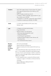
3 B760M Pro RS/D4 WiFiB760M Pro RS/D4 Graphics • Intel® UHD Graphics Built-in Visuals and the VGA outputs can be supported only with processors which are GPU integrated. • Intel® X e Graphics Architecture (Gen 12) • 1 x HDMI 2.1 TMDS Compatible, supports HDCP 2.3 and max. resolution up to 4K 60Hz • ...
Page 8 - USB; * All USB ports support ESD Protection; Storage; x SPI TPM Header
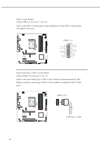
4 USB • 2 x USB 3.2 Gen1 Type-C (1 Rear, 1 Front) • 5 x USB 3.2 Gen1 Type-A (3 Rear, 2 Front) • 6 x USB 2.0 (2 Rear, 4 Front) * All USB ports support ESD Protection Rear Panel I/O • 2 x Antenna Ports (For B760M Pro RS/D4 WiFi) • 2 x Antenna Mounting Points (For B760M Pro RS/D4) • 1 x PS/2 Mouse/Keyb...
Page 9 - OS
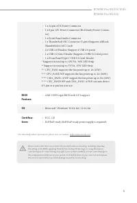
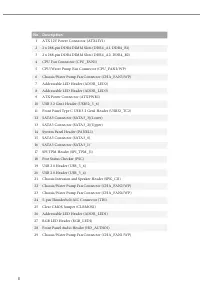
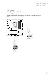
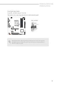
5 B760M Pro RS/D4 WiFiB760M Pro RS/D4 • 1 x 24 pin ATX Power Connector • 1 x 8 pin 12V Power Connector (Hi-Density Power Connec-tor) • 1 x Front Panel Audio Connector • 1 x Thunderbolt AIC Connector (5-pin) (Supports ASRock Thunderbolt 4 AIC Card) • 2 x USB 2.0 Headers (Support 4 USB 2.0 ports) • 1 ...
Page 10 - I n t e l; Motherboard Layout
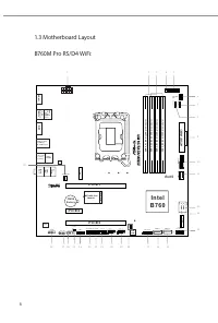
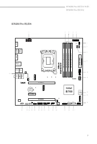
6 I n t e l B 7 6 0 A T X P W R 1 H D L E D R E S E T P L E D P W R B T N PA N E L 1 1 1 1 2 C P U _ FA N 1 3 1 P C I E 1 1 D D R 4 _ A 2 ( 6 4 b it , 2 8 8 -p in m o d u le ) D D R 4 _ A 1 ( 6 4 b it , 2 8 8 -p in m o d u le ) D D R 4 _ B 2 ( 6 4 b it , 2 8 8 -p in m o d u le ) D D R 4 _ B 1 ( 6 4 ...
Page 14 - HDMI Port
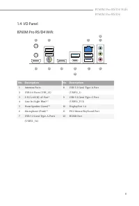
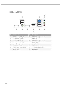
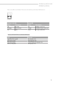
10 No. Description No. Description 1 USB 2.0 Ports (USB_12) 7 USB 3.2 Gen1 Type-A Port 2 2.5G LAN RJ-45 Port* (USB32_1) 3 Line In (Light Blue)** 8 USB 3.2 Gen1 Type-C Port 4 Front Speaker (Lime)** (USB32_TC1) 5 Microphone (Pink)** 9 DisplayPort 1.4 6 USB 3.2 Gen1 Type-A Ports 10 PS/2 Mouse/Keyboard ...
Page 18 - WiFi Antennas Installation Guide; Step 2
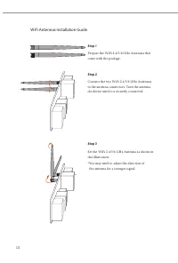
14 WiFi Antennas Installation Guide Step 1 Prepare the WiFi 2.4/5/6 GHz Antennas that come with the package. Step 2 Connect the two WiFi 2.4/5/6 GHz Antennas to the antenna connectors. Turn the antenna clockwise until it is securely connected. Step 3 Set the WiFi 2.4/5/6 GHz Antenna as shown in the ...
Page 19 - Pre-installation Precautions; Hold components by the edges and do not touch the ICs.; Chapter 2 Installation
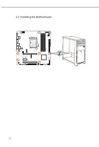
15 B760M Pro RS/D4 WiFiB760M Pro RS/D4 This is a Micro ATX form factor motherboard. Before you install the motherboard, study the configuration of your chassis to ensure that the motherboard fits into it. Pre-installation Precautions Take note of the following precautions before you install motherbo...
Page 20 - Installing the CPU
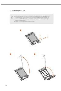
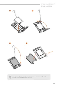
16 2.1 Installing the CPU 1. Before you insert the 1700-Pin CPU into the socket, please check if the PnP cap is on the socket, if the CPU surface is unclean, or if there are any bent pins in the socket. Do not force to insert the CPU into the socket if above situation is found. Otherwise, the CPU wi...
Page 22 - Installing the CPU Fan and Heatsink
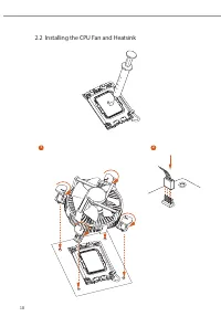
18 2.2 Installing the CPU Fan and Heatsink 1 2 CPU_F AN
Page 23 - Recommended Memory Configuration; DIMMs
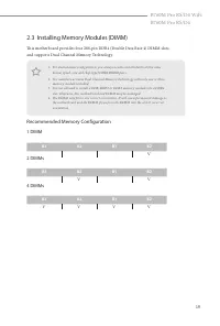
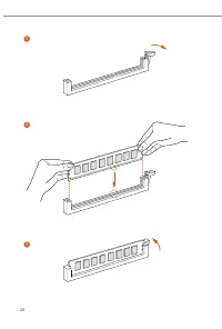
19 B760M Pro RS/D4 WiFiB760M Pro RS/D4 2.3 Installing Memory Modules (DIMM) This motherboard provides four 288-pin DDR4 (Double Data Rate 4) DIMM slots, and supports Dual Channel Memory Technology. Recommended Memory Configuration 1 DIMM 2 DIMMs 4 DIMMs A1 A2 B1 B2 V A1 A2 B1 B2 V V A1 A2 B1 B2 V V ...
Page 25 - Connecting the Front Panel Header; System Panel Header
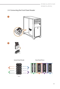
21 B760M Pro RS/D4 WiFiB760M Pro RS/D4 2.4 Connecting the Front Panel Header A B C D 1 2 32 :(56: 5( 6( 76 : 32 : (5/( ' 32 : (5 / (' + ' ' /(' 3$1(/ Power SW (-) RESET SW (+) HDD LED (-) HDD LED (+) 1 2 9 10 RESET SW (-) Power SW (+) Power LED (-) Power LED (+) A B C D PANEL1 HD D L ED RESE T SW Sy...
Page 26 - Installing the Motherboard
Page 27 - Installing SATA Drives; Optical Drive
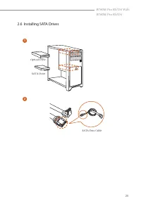
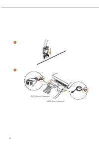
23 B760M Pro RS/D4 WiFiB760M Pro RS/D4 2.6 Installing SATA Drives 1 2 Optical Drive SATA Drive SATA Data Cable
Page 29 - Installing a Graphics Card
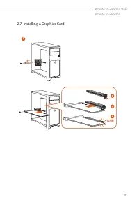
25 B760M Pro RS/D4 WiFiB760M Pro RS/D4 2.7 Installing a Graphics Card 1 CLICK!
Page 30 - There are 3 PCIe slots on the motherboard.; PCIe Slot Configurations; Single Graphics Card; Mode
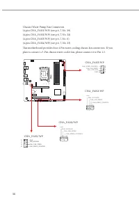
26 For a better thermal environment, please connect a chassis fan to the motherboard’s chassis fan connector (CHA_FAN1~4/WP) when using multiple graphics cards. Expansion Slots (PCIe Slots) There are 3 PCIe slots on the motherboard. PCIe slots: PCIE1 (PCIe 4.0 x16 slot) is used for PCIe x16 lane wid...
Page 31 - Connecting Peripheral Devices
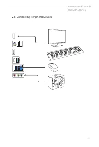
27 B760M Pro RS/D4 WiFiB760M Pro RS/D4 2.8 Connecting Peripheral Devices
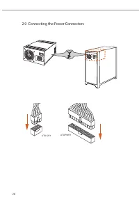
Page 32 - Connecting the Power Connectors
Page 34 - CLRMOS1
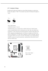
30 2.11 Jumpers Setup The illustration shows how jumpers are setup. When the jumper cap is placed on the pins, the jumper is “Short”. If no jumper cap is placed on the pins, the jumper is “Open”. Clear CMOS Jumper (CLRMOS1) (see p.6, 7, No. 25)CLRMOS1 allows you to clear the data in CMOS. The data i...
Page 35 - Onboard Headers and Connectors
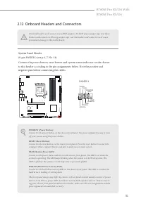
31 B760M Pro RS/D4 WiFiB760M Pro RS/D4 2.12 Onboard Headers and Connectors System Panel Header(9-pin PANEL1) (see p.6, 7, No. 14)Connect the power button, reset button and system status indicator on the chassis to this header according to the pin assignments below. Note the positive and negative pin...
Page 42 - ATXPWR1
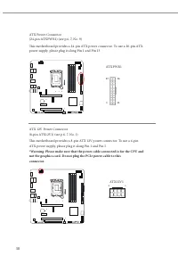
38 ATX Power Connector(24-pin ATXPWR1) (see p.6, 7, No. 9)This motherboard provides a 24-pin ATX power connector. To use a 20-pin ATX power supply, please plug it along Pin 1 and Pin 13. ATX 12V Power Connector(8-pin ATX12V1) (see p.6, 7, No. 1)This motherboard provides a 8-pin ATX 12V power connect...
Page 44 - Connect your RGB LED strip to the; RGB LED; on the motherboard.
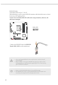
40 RGB LED Header(4-pin RGB_LED1) (see p.6, 7, No. 27)This RGB header is used to connect RGB LED extension cable which allow users to choose from various LED lighting effects. Caution: Never install the RGB LED cable in the wrong orientation; otherwise, the cable may be damaged. 1. Never install the...
Page 45 - the cable may be damaged.; on
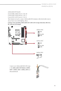
41 B760M Pro RS/D4 WiFiB760M Pro RS/D4 Addressable LED Headers(3-pin ADDR_LED1) (see p.6, 7, No. 26)(3-pin ADDR_LED2) (see p.6, 7, No. 7)(3-pin ADDR_LED3) (see p.6, 7, No. 8)These headers are used to connect Addressable LED extension cables which allow users to choose from various LED lighting effec...
Page 47 - Post Status Checker
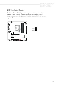
43 B760M Pro RS/D4 WiFiB760M Pro RS/D4 2.13 Post Status Checker Post Status Checker (PSC) diagnoses the computer when users power on the machine. It emits a red light to indicate whether the CPU, memory, VGA or storage is dysfunctional. The lights go off if the four mentioned above are function-ing ...
Page 48 - Find the nut location to be used.
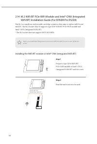
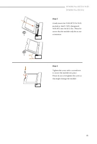
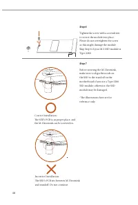
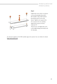
44 2.14 M.2 WiFi/BT PCIe WiFi Module and Intel® CNVi (Integrated WiFi/BT) Installation Guide (For B760M Pro RS/D4) The M.2 is a small size and versatile card edge connector that aims to replace mPCIe and mSATA. The M.2 Socket (Key E) supports type 2230 WiFi/BT PCIe WiFi module and Intel® CNVi (Integ...
Page 50 - Installing the M.2 SSD Module; Nut Location
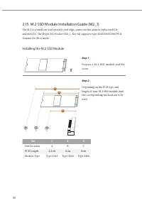
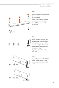
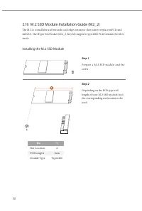
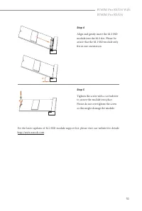
46 2.15 M.2 SSD Module Installation Guide (M2_1) The M.2 is a small size and versatile card edge connector that aims to replace mPCIe and mSATA. The Hyper M.2 Socket (M2_1, Key M) supports type 2242/2260/2280 PCIe Gen4x4 (64 Gb/s) mode. Installing the M.2 SSD Module Step 1 Prepare a M.2 SSD module a...
Page 59 - WARNING; THIS PRODUCT CONTAINS A BUTTOON BATTERY; AUSTRALIA ONLY
The terms HDMI ® and HDMI High-Definition Multimedia Interface, and the HDMI logo are trademarks or registered trademarks of HDMI Licensing LLC in the United States and other countries. WARNING THIS PRODUCT CONTAINS A BUTTOON BATTERY If swallowed, a button battery can cause serious injury or death. ...
Page 60 - for disposal of electronic products.; CE Warning; uncontrolled environment.
ASRock INC. hereby declares that this device is in compliance with the essential require- ments and other relevant provisions of related UKCA Directives. Full text of UKCA decla- ration of conformity is available at: http://www.asrock.com ASRock INC. hereby declares that this device is in compliance...
Page 61 - Radio transmit power per transceiver type; Function; WiFi
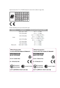
Operations in the 5.15-5.35GHz band are restricted to indoor usage only. Radio transmit power per transceiver type Function Frequency Maximum Output Power (EIRP) WiFi 2400-2483.5 MHz 18.5 + / -1.5 dbm 5150-5250 MHz 21.5 + / -1.5 dbm 5250-5350 MHz 18.5 + / -1.5 dbm (no TPC) 21.5 + / -1.5 dbm (TPC) 54...