Page 3 - Safety Warnings
2 Safety Warnings INDD94 & AID864DD • The appliance is not intended for use by persons (including children) with reduced physical, sensory or mental capabilities, or lack of experience and knowledge, unless they have been given supervised or instruction concerning use of the appliance by a respo...
Page 6 - GENERAL; The aspiration system is composed by three appliances:
5 I GENERAL This guide describes the appliance and its use. This guide is an integral part of the appliance itself and has to be retained with the appliance and ALWAYS accompany it, even in case of its assignment to another owner or user or in case the cooker hood is moved to another installation pl...
Page 7 - II; WARNINGS; CAUTION: This appliance has not been designed for gas hobs.
6 II WARNINGS CAUTION: This appliance has not been designed for gas hobs. • This appliance is manufactured according to the safety standards in force. • The use of this appliance must not be other than the one it has been designed for; this means as an induction hob for cooking in domestic kitchens ...
Page 8 - Using the appliance
7 • Do not use the appliance for room heating; • If there is a wall power outlet located near the appliance and another appliance is plugged into it, make sure the power cord does not come into contact with the hot cooking zones; • It is forbidden to pull, disconnect, twist the electrical wiring out...
Page 10 - Other protections; of the pan must have to cover as much as possible the cooking zone.; NEVER; III; INSTALLATION; III.1 PRELIMINARY INDICATIONS; is normal to have some left at the end of the installation.
9 Other protections • Note sure that the container pan is always centered on the cooking zone. The bottom of the pan must have to cover as much as possible the cooking zone. • For the users of pacemaker, the magnetic field could influence its operating. We recommend getting information to the retail...
Page 15 - Installation of the induction hob may be flush or non-flush.
14 III.2.a INDUCTION HOB INSTALLATION To leave the necessary space for the air pipes it is important to install the induction hob with the centerline more than 300mm away from the wall on the back that may be present. Installation of the induction hob may be flush or non-flush. NON-FLUSH INSTALLATIO...
Page 17 - between the ventilation of the lower
16 · It is necessary to ensure adequate ventilation on the front side of the base so that the air can properly flow (Fig. 3.2.a.4). · If a drawer is below the hob, to guarantee a good air circulation and good cooling system of the induction hob, maintain a gap of 30 mm minimum between the ventilatio...
Page 19 - The air exit can be on the left or on the right of the kitchen base.
18 The next step is to determine the exit of the fumes according with the installation needs. The air exit can be on the left or on the right of the kitchen base. To do this, remove the screws, detach the cover (3.2.b.3 –X) and the cup (3.2.b.3–Y) invert the aspirator outlet (3.2.b.3 –Z) and place t...
Page 20 - moving the pipe inside the motor box.
19 After installing the induction hob as paragraph III.2.a INDUCTION HOB INSTALLATION, align the suction unit with the hob (Fig. 3.2.c.1) by positioning it inside the cut of the base of the piece of furniture previously made (Fig. 3.2.b.1). If the length of the metal pipe is not enough to reach the ...
Page 21 - The holes that now are empty can be cover with the cup supplied.
20 The front panel and the pipe are fixed together with 3 screws (Fig. 3.2.c.3) removing these, the pipe can slide to the upper position and then it can be re–fix with the same screws. The holes that now are empty can be cover with the cup supplied. Now the motor box can be inserted in the housing a...
Page 22 - III.3 ELECTRICAL CONNECTION; comply with the regulations in force.
21 III.3 ELECTRICAL CONNECTION The electrical connection must be carried out ONLY by qualified technicians. The electrical protection of the electrical connection upstream of the equipment must comply with the regulations in force. The appliance is composed by three devices that must be separately c...
Page 23 - These appliances must be earthed.; Two types of connections to the network are possible:
22 These appliances must be earthed. Two types of connections to the network are possible: 1. Using a standard plug connected (Fig. 3.3.1) to the power cord and inserted into an accessible socket outlet (to be disconnected during service operations). Make sure that the plug is accessible even after ...
Page 24 - Aspirator connection procedure:; First of all, connect the motor box to the induction hob:; been equipped with a faulty earth connection.
23 Aspirator connection procedure: First of all, connect the motor box to the induction hob: • Connect the flat connector (male-female) to the mainboard, with the control’s connector dropping from the induction hob (Fig. 3.3.3). · Protection against the parts under tension must be ensured after the ...
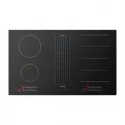
Page 25 - IV; OPERATION; IV.1 DESCRIPTION OF THE INDUCTION HOB
24 IV OPERATION IV.1 DESCRIPTION OF THE INDUCTION HOB IV.1.a TECHNICAL CHARACTERISTICS Power level detail: Power limitation when Ø 180 heaters are working simultaneously (no bridge function): Total Power 3600W IV.1.b BASIC CONTROL CHARACTERISTICS • Auto Lock function • Fast Boil function • Bridge fu...
Page 26 - IV.2 USE OF THE INDUCTION HOB; is touched from heater2, nothing happens.; switched ON; case of residual heat or error status of the cooking zone.
25 GENERAL KEYS - 1 key for switching On/Off the Cooktop [ON/OFF] and unlocking the keyboard. - 2 keys to “time selection”. HEATER KEYS - 1 selection key for each heater’s timer [Heater_timer_selection] / Warm function - 1 Slider for each heater to select cook set ((0)-1-2-….P) BUZZER SOUNDS IV.2 US...
Page 27 - The cooktop is; switched Off; the heaters are switched Off.
26 ¾ If the selection of a heater is not done in 10 seconds, the cooktop will be turned off automatically. The cooktop is switched Off by touching the [ON/OFF] key for 1 sec. A beep sounds and all the heaters are switched Off. IV.2.c SWITCH ON A HEATER ZONE When a cooktop is on (On/Off status LED is...
Page 34 - Power level
33 IV.2.o AUTOMATIC SAFETY OFF If the power level is not changed during a preset time, the corresponding heater turns off automatically. The maximum time a heater can stay on, depends on the selected cooking level. IV.2.p RESIDUAL HEAT INDICATION After a zone has been switched off, an “H” will be di...
Page 35 - with ferromagnetic bottom.; Not adapted materials:
34 IV.2.r DISPLAYING SPECIAL STATUSES IN TOUCH CONTROL The corresponding heater display alternates between two characters depending on the status. Special status (Visualization Priority Order) Start conditions End conditions Action Heater status Heater Display fore Heater Display back Power incremen...
Page 36 - IV.4 COOKER HOOD OPERATION
35 Certain pans can make noise when they are placed on an induction cooking zone. This noise doesn’t mean any failure on the appliance and doesn’t influence the cooking operating. IV.3.b PAN DIMENSION However, the bottom of this pan must have a minimum of diameter according to the corresponding cook...
Page 41 - CLEANING AND MAINTENANCE; V.1 INDUCTION HOB CLEANING; Switch-off the appliance before cleaning.; V.2 COOKER HOOD CLEANING; order to remove any residual glue or impurities of any kind.; Warning! Products that are NOT to be used are:
40 V CLEANING AND MAINTENANCE V.1 INDUCTION HOB CLEANING Switch-off the appliance before cleaning. Do not clean the hob if the glass is too hot because they are risk of burn. • Remove light marks with a damp cloth with washing up liquid diluted in a little water. Then rinse with cold water and dry t...
Page 42 - Ordinary cleaning; cause abrasive phenomena.; VI; WHAT TO DO IN CASE OF A PROBLEM; staff
41 Ordinary cleaning Ordinary cleaning should be performed before excessive build-up of dirt can occur which can cause abrasive phenomena. Before performing the washing operations, any dust particles should be removed by air or aspirated, so as to avoid rubbing on the surface. Where water has been u...
Page 43 - VII; DISCONTINUATION, DISASSEMBLY AND WASTE DISPOSAL; VII.1 DISCONTINUATION
42 VI.1 ERRORS / ALARMS The corresponding heater display alternates between two characters depend on the Error. Event Action Error on Display ON-OFF Safety error Off (*) FA Software Safety error Off (*) F0 Capacitive key sensitivity error Off (*) Fb NTC Short-circuit error Off (*) FE NTC open error ...
Page 44 - VII.3 ENVIRONMENT PRESERVATION
43 VII.2 DISASSEMBLY Disassembly requires that the appliance is accessible for disassembly and has been disconnected from the power supply. To do so, you need: Loose screws and fixing brackets Remove any silicone seals Disconnect the motor and the channel from the hob Take the top of the h...
Page 46 - Warranty Card; WARRANTY REGISTRATION
Warranty Card Worldwide Appliances Pty Limited A.B.N. 45868077422Distributed by Eurolinx pty Ltd Office: 48-50 Moore Street, Leichhardt N.S.W 2040 Post: Locked Bag 3000, Annandale, N.S.W 2038 P: 1300 694 583 WARRANTY REGISTRATION Your ongoing satisfaction with your artusi product is important to us....
Page 47 - All warranty service calls must be booked via; continued; Warranty Card tear off
4. Time for Claim under the WarrantyYou must make any claim under this Warranty within twenty eight (28) days after the occurrence of an event which gives rise to a claim pursuant to the Warranty, by booking a service call on the telephone number below. 5. Proof of PurchaseCustomers must retain proo...