Whirlpool WVW73UC0LS - User Manual
Whirlpool WVW73UC0LS Range Hood – User Manual, read for free online in PDF format. We hope this helps you resolve any issues you may have. If you have further questions, please contact us through the contact form.
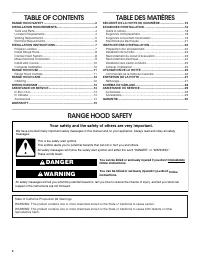
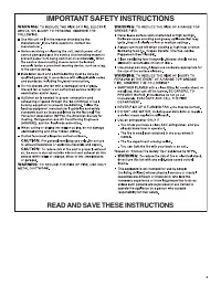


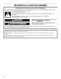
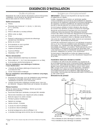
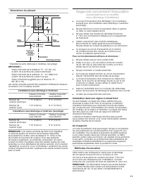
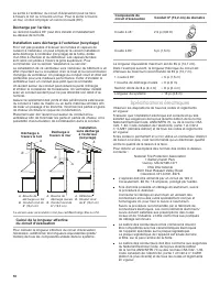
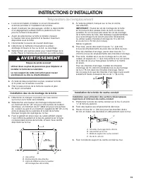
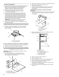
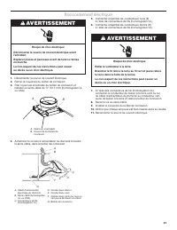
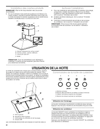
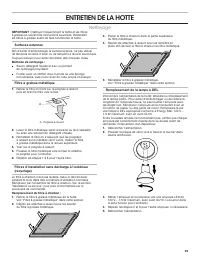
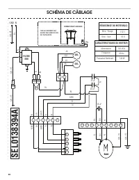


Table of Contents:
- Page 2 – Your safety and the safety of others are very important.; DANGER
- Page 3 – IMPORTANT SAFETY INSTRUCTIONS; READ AND SAVE THESE INSTRUCTIONS
- Page 4 – INSTALLATION REQUIREMENTS; Tools and Parts; Location Requirements
- Page 5 – Venting Requirements
- Page 6 – Electrical Requirements
- Page 7 – INSTALLATION INSTRUCTIONS; Prepare Location; WARNING
- Page 9 – Make Electrical Connection
- Page 10 – RANGE HOOD USE; Range Hood Controls
- Page 11 – RANGE HOOD CARE; Cleaning
- Page 12 – WIRING DIAGRAM; TULUM ES; PRINTING AREA; * DO NOT PRINT DASHED LINE; DRAFT; Carta metallizzata 80x85 / Metallic Sticky Paper 80x85
- Page 13 – ASSISTANCE OR SERVICE; In Canada
- Page 14 – SÉCURITÉ DE LA HOTTE DE CUISINIÈRE; Votre sécurité et celle des autres est très importante.; AVERTISSEMENT
- Page 15 – IMPORTANTES INSTRUCTIONS DE SÉCURITÉ; LIRE ET CONSERVER CES INSTRUCTIONS
- Page 16 – EXIGENCES D’INSTALLATION; Outils et pièces; Exigences d’emplacement
- Page 17 – Exigences concernant l’évacuation; (seulement pour un modèle
- Page 18 – Spécifications électriques
- Page 19 – INSTRUCTIONS D’INSTALLATION; Préparation de l’emplacement
- Page 20 – Raccordement du circuit d’évacuation
- Page 21 – Raccordement électrique
- Page 22 – UTILISATION DE LA HOTTE; Commandes de la hotte de cuisinière
- Page 23 – ENTRETIEN DE LA HOTTE; Nettoyage
- Page 24 – SCHÉMA DE CÂBLAGE
- Page 25 – ASSISTANCE OU SERVICE; Au Canada
- Page 26 – Remarques
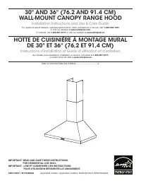
30" AND 36" (76.2 AND 91.4 CM)
WALL‑MOUNT CANOPY RANGE HOOD
Installation Instructions and Use & Care Guide
For questions about features, operation/performance, parts, accessories or service, call:
1-800-253-1301
or visit our website at
www.whirlpool.com
In Canada, call
1-800-807-6777
or visit our website at
www.whirlpool.ca
HOTTE DE CUISINIÈRE À MONTAGE MURAL
DE 30" ET 36" (76,2 ET 91,4 CM)
Instructions d’installation et Guide d’utilisation et d’entretien
Au Canada, pour assistance, installation ou service, composer le
1-800-807-6777
ou visiter notre site Web à
www.whirlpool.ca
Table of Contents/Table des matières ..................................... 2
LIB0173497 / W11549254A
IMPORTANT: READ AND SAVE THESE INSTRUCTIONS.
FOR RESIDENTIAL USE ONLY.
IMPORTANT : LIRE ET CONSERVER CES INSTRUCTIONS.
POUR UTILISATION RÉSIDENTIELLE UNIQUEMENT.
Applicable models / Applicable modèles: WVW73UC0LS, WVW73UC6LS
"Loading the manual" means you need to wait until the file loads and becomes available for online reading. Some manuals are very large, and the time they take to appear depends on your internet speed.
Other Manuals for Whirlpool WVW73UC0LS
Summary
2 TABLE OF CONTENTS TABLE DES MATIÈRES RANGE HOOD SAFETY You can be killed or seriously injured if you don't immediately You can be killed or seriously injured if you don't follow All safety messages will tell you what the potential hazard is, tell you how to reduce the chance of injury, and tell yo...
3 IMPORTANT SAFETY INSTRUCTIONS READ AND SAVE THESE INSTRUCTIONS
4 INSTALLATION REQUIREMENTS Tools and Parts Gather the required tools and parts before starting installation. Read and follow the instructions provided with any tools listed here. Tools Needed ■ Level ■ Drill with 1 1 / 4 " (3 cm), 3 / 8 " (9.5 mm), and 3 / 16 " (4.8 mm) drill bits ■ Pe...