Whirlpool GMF7522IXL - User Manual
Whirlpool GMF7522IXL Hob – User Manual, read for free online in PDF format. We hope this helps you resolve any issues you may have. If you have further questions, please contact us through the contact form.


Table of Contents:
- Page 2 – PRECAUTIONS AND GENERAL ADVICE; PROVISION FOR VENTILATION; ROOM VENTILATION; INSTALLATION; TECHNICAL INFORMATION FOR THE INSTALLER
- Page 3 – GAS CONNECTION; ELECTRICAL CONNECTION
- Page 4 – SERVICE INSTRUCTIONS; WARNING; Disconnect power before servicing.; CLEANING THE HOB PARTS
PRODUCT DESCRIPTION SHEET
EN
5019 300 02568
AU
To get full satisfaction from the hob, please read these instructions carefully and keep them for future consultation.
LIGHTING THE BURNERS
•
To ignite one of the burners, turn the relative knob anti-clockwise to the maximum flame setting .
•
Press the knob against the control panel to ignite the burner.
•
After the burner has ignited, keep the knob pressed for about 5 seconds to allow the thermocouple to warm up.
This burner safety device shuts off the gas supply to the burner if the flame goes out accidentally (because of sudden
draught, an interruption in the gas delivery, boiling over of liquids, etc.).
•
The device must not be pressed for more than 15 sec. If, after that time has elapsed, the burner does not remain lit,
wait at least one minute before trying to light it again.
-
The burner might go out when the knob is released. This means that the thermocouple has not warmed up enough.
In this case, repeat the operations described above.
RACTICAL ADVICE FOR USING THE BURNERS
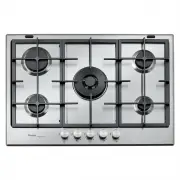
1. Removable panstand grids
2. Semi-rapid burner FC
3. Auxiliary burner
4. Semi-rapid burner BC
5. Rapid burner
6. 2 ring burner
7. Auxiliary burner control knob
8. Rapid burner control knob
9. 2 ring burner control knob
10. Semi-rapid burner FC control knob
11. Semi-rapid burner BC control knob
Symbols
Tap closed
Maximum flame
Minimum flame
3
2
7
8
10
9
6
11
1
4
5
This hob has burners of different diameters. For better burner performance,
please stick to the following rules:
-
Use pots and pans with bottoms the same width as that of the burners or
slightly larger (see table on the right).
-
Only use flat-bottomed pots and pans.
-
Use the correct amount of water for cooking foods and keep the pot covered.
-
Make sure pots on the grates do not protrude beyond the edge of the hob
-
In the case of pans with convex bottoms (WOK), use the support grille
(not included), which should be positioned only on the 2 ring burner.
IMPORTANT: improper use of the grids can result in damage to the hob: do
not position the grids upside down or slide them across the hob.
Do not use:
-
Cast iron griddles, ollar stones, terracotta pots and pans.
-
Heat diffusers such as metal mesh, or any other types.
-
Two burners simultaneously for one receptacle (e.g. fish kettle).
Burner
Pot Ø
2 ring
From 24 to 30 cm
Rapid
From 24 to 26 cm
Semi-rapid BC
From 16 to 24 cm
Semi-rapid FC
From 16 to 22 cm
Auxiliary
From 8 to 14 cm
BC: means Back
Centre
FC: means Front
Centre
DIMENSIONS AND DISTANCES TO BE MAINTAINED (mm)
NOTE: In case of installation of a hood above the cooktop, please refer to the hood instructions for the correct distance.
NOTE: The indicated clearance dimensions are applicable to all non-combustible materials.
ELECTRIC SUPPLY: 220-240 V ~ 50/60 Hz 0.6 VA
WOK ADAPTER
Gas Type
Natural @ 1.00 kPa
(test point pressure)
Universal LP @ 2.75 kPa
(inlet pressure)
BURNER
Nominal Gas
Consumption (MJ/h)
Nominal Injector Size
(mm)
Nominal Gas
Consumption (MJ/h)
Nominal Injector Size
(mm)
FRONT RHS Auxiliary
4.1
0.90
3.4
0.52
REAR CHS Semi-Rapid C
6.8
1.17
5.5
0.67
FRONT CHS Semi-Rapid C
6.8
1.17
5.5
0.67
REAR RHS Rapid
9.6
1.40
9.5
0.85
MIDDLE LHS Wok C
17.6
1.92
15.0
1.08
TOTAL
44.9
-
38.9
-
"Loading the manual" means you need to wait until the file loads and becomes available for online reading. Some manuals are very large, and the time they take to appear depends on your internet speed.
Was this manual helpful?
About this manual
- Brand
- Whirlpool
- Model
- GMF7522IXL
- Document type
- User Manual
- Category
- Hob
- Language(s)
- English
- Pages
- 4
- File size
- 389.1 KB
- Format
Summary
PRECAUTIONS AND GENERAL ADVICE To get full satisfaction from your hob, please read these instructions carefully and keep them for future consultation• These instructions are only valid for those Countries where the destination abbreviations are mentioned on the product description sheet and on the h...
INSTALLATION GAS CONNECTION 1. Check the “gas type” sticker attached to the hotplate. Details of the injector sizes used are recorded on the data plate located on the base of the appliance. 2. This appliance shall be installed in accordance with installation requirements of the local gas authority o...
ADJUSTMENT TO DIFFERENT TYPES OF GAS If the appliance is intended to operate with a different gas from the gas type stated on the rating plate change the injectors.Use pressure regulators suitable for the gas pressure indicated in the Product Description Sheet.• The gas nozzles must be changed by Af...
Ask a question
Related manuals
Popular Whirlpool Hobs
More Whirlpool Hobs models
 Whirlpool WCGK7536PS User Manual
 Whirlpool WCI55US0JB User Manual
 Whirlpool ACM795BA User Manual
 Whirlpool ACM804BA User Manual
 Whirlpool SMP658CNEIXL User Manual
 Whirlpool W5CE1522FB User Manual
 Whirlpool WCC31430AB User Manual
 Whirlpool WCC31430AW User Manual
 Whirlpool WCE55US0HB User Manual
 Whirlpool WCE55US0HS User Manual
 Whirlpool WCE55US0HW User Manual
 Whirlpool WCE77US0HB User Manual
 Whirlpool WCE77US0HS User Manual
 Whirlpool WCE77US6HS User Manual