Page 2 - Instructions; General safety instructions; • WARNING: If the surface is
Instructions 4 1 Instructions 1.1 General safety instructions Risk of personal injury • During use the appliance and its accessible parts become very hot. Never touch the heating elements during use. • Never try to put out a fire or flames with water: turn off the appliance and smother the flames wi...
Page 3 - store items on the cooking surfaces.
Instructions 5 EN • WARNING: Danger of fire: do not store items on the cooking surfaces. • Means for disconnection of appliance must be incorporated in the fixed wiring in accordance with the wiring rules. • Make sure that the flame-spreader crowns are correctly positioned in their housings with the...
Page 4 - Risk of damaging the appliance
Instructions 6 Risk of damaging the appliance • Do not use harsh abrasive cleaners or sharp metal scrapers to clean glass since they can scratch the surface, which may result in shattering of the glass. • Use wooden or plastic utensils.• Do not seat on the appliance.• Do not obstruct ventilation ope...
Page 6 - For this appliance
Instructions 8 • This domestic appliance is not connected to a device for extracting combustion products. It must be installed and connected in accordance with current installation regulations. Pay particular attention to the relevant requirements regarding ventilation. For this appliance • Switch o...
Page 7 - This user manual
Instructions 9 EN 1.4 This user manual This user manual is an integral part of the appliance and must therefore be kept in its entirety and within the user’s reach for the whole working life of the appliance.Read this user manual carefully before using the appliance. 1.5 Identification plate The ide...
Page 8 - How to read the user manual
Instructions 10 1.7 How to read the user manual This user manual uses the following reading conventions: 1. Sequence of instructions for use.• Standalone instruction. Instructions General information on this user manual, on safety and final disposal. Description Description of the appliance and its ...
Page 9 - Description; General description; SX
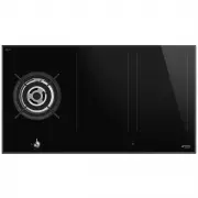
Description 11 EN 2 Description 2.1 General description 90 cm UR* = Ultra rapid SX = Left induction cooking zone DX = Right induction cooking zone F = Front plate R = Rear plate C = General controls zone 2.2 Symbols Burner knobs For lighting and adjusting the hob burners. Press and turn the knobs an...
Page 10 - Advantages of induction cooking
Description 12 Maximum absorbed power table (Watt) * power levels are approximate and may vary according to the pan used or the settings made. Advantages of induction cooking • Energy saving thanks to the direct transmission of energy to the pan (suitable magnetisable cookware is required) compared ...
Page 11 - Available accessories; Wok support
Description 13 EN 2.3 Available accessories Wok support Useful when using a wok. The accessories intended to come into contact with food are made of materials that comply with the provisions of current legislation. Original supplied and optional accessories can be requested to Authorised Assistance ...
Page 12 - Use; Improper use
Use 14 3 Use 3.1 Instructions Improper use Danger of burns • Make sure that the flame-spreader crowns are correctly positioned in their housings with their respective burner caps. • Do not leave the appliance unattended during cooking operations where fats or oils could be released. • Oils and fats ...
Page 13 - A gas leak can cause an explosion.; Using the gas burners
Use 15 EN 3.2 Precautions A gas leak can cause an explosion. If you smell gas or there are faults in the gas system:• Immediately turn off the gas supply or close the valve on the gas cylinder. • Extinguish all naked flames and cigarettes. • Do not turn on power switches or appliances and do not rem...
Page 14 - Correct positioning of the pan supports
Use 16 Correct positioning of the flame-spreader crowns and burner caps Before lighting the hob burners, make sure that the flame-spreader crowns are correctly positioned in their housings with their respective burner caps. Make sure that the holes in the burners are aligned with the igniters and th...
Page 15 - Trivets and reduction pan supports; Using the induction hot plates; Switching on the hob for the first time
Use 17 EN Trivets and reduction pan supports The trivet/support must be rested on the hob pan supports. Make sure they are properly positioned. Using a griddle A few precautions are necessary if you wish to use a griddle:• The griddle can be pre-heated with the burner on maximum power for no more th...
Page 16 - Minimum cookware diameter
Use 18 Minimum cookware diameter Make sure that the minimum diameter of the pans are those indicated in the following table, for both configurations. * Values for one pan, if two pans are used refer to the values for a single hot plate configuration.Bear in mind the following:• Do not allow the pans...
Page 17 - Limiting the cooking duration
Use 19 EN Limiting the cooking duration The hob has an automatic device which limits the duration of use. If the cooking zone settings are not changed, the maximum duration of operation for each zone depends on the power level selected.When the device for limiting the duration of use is activated, t...
Page 18 - Power levels
Use 20 Power levels The power in the cooking zone can be adjusted to various levels. The table shows the levels suitable for various types of cooking. * see Booster and Double Booster function Switching the hob on and off Keep the On/Off button pressed in for at least 1 second to activate the hob. P...
Page 19 - Switching off the cooking zone
Use 21 EN 2. Move your finger to the left or right on the scroll bar to select the power level, from to or activate the Booster function (see “Booster Function”). The display of the zone being used will indicate the selected power level. Switching off the cooking zone 1. Move your finger all the way...
Page 20 - Double Booster Function
Use 22 After switching on the hob and having selected a cooking zone:1. Place a finger on the left-hand side of the scroll bar. The display of the cooking zone used will turn on: the power value indicated is . 2. Move your finger all the way to the right of the scroll bar to select the Booster funct...
Page 21 - Multizone function; and
Use 23 EN Multizone function After switching on the hob:1. Place a finger simultaneously on the buttons of two cooking zones one above the other. After a short beep, the symbol will appear next to the button of the rear zone. The Multizone function is now active.2. Use the left-hand scroll bar to se...
Page 22 - To deactivate the Multizone function:
Use 24 Example of incorrect pan position To deactivate the Multizone function: Simultaneously press the buttons of the cooking zones on which the Multizone function is active. The symbol disappears and the two zones can be regulated separately. Cooking guidelines The table below shows the power valu...
Page 23 - Special functions; Warning Function
Use 25 EN 3.6 Special functions Warning Function To activate the Warming function, first turn on the hob, then:1. Select a cooking zone. 2. Press the button to activate the function. The symbol appears on the display of the selected cooking zone. To deactivate the Warming function:1. Select the cook...
Page 24 - Controls lock; Additional functions; Rapid heating
Use 26 The symbol appears on the front zone display and the symbol appears on the rear zone display. The scroll bar will be set automatically to level 8 . (preheating stage) After two minutes of operation, the power will be reduced to level 6 . Press the button and use the scroll bar to modify the p...
Page 25 - Modifying or deactivating the timer
Use 27 EN 2. Use the + and - buttons to select the required time. • The first digit on the left is used to select the hours, the middle one to set the tens of minutes and the one on the right the minutes. 3. After 10 seconds, the timer will start the countdown. 4. When the time elapses, a series of ...
Page 26 - Modifying or deactivating timed cooking
Use 28 At the end of the set time, a buzzer tells the user that the Minute minder has finished.5. Press any button to deactivate the buzzer. Modifying or deactivating timed cooking To modify timed cooking during the countdown: 1. Press the On/Off button to activate the hob (if it is in stand-by). 2....
Page 27 - Accessing the user menu; Model
Use 29 EN Accessing the user menu 1. If the hob is off, switch it on using the On/Off button . 2. Press again within 3 seconds to switch it off; the button starts to flash. Press and hold . 3. The following will be shown on the cooking zones display: 4. Press all the buttons of the cooking zones in ...
Page 28 - Exiting the user menu
Use 30 • 0 : minimum volume. • 3 : maximum volume. Option U3 modifies the volume of the signals (for example the sound of the alarm when the timer has finished). 4 levels can be selected.• 0 : minimum volume. • 3 : maximum volume. Option U4 modifies the brightness of the display. 10 levels can be se...
Page 29 - Practical advice
Use 31 EN 3.10 Practical advice • For better burner efficiency and to minimise gas consumption, use pans with lids and of suitable size for the burner, so that the flames do not reach up the sides of the pan. Once the contents come to the boil, turn down the flame far enough to ensure that the liqui...
Page 30 - Cleaning and maintenance; Cleaning the appliance; Ordinary daily cleaning
Cleaning and maintenance 32 4 Cleaning and maintenance 4.1 Instructions 4.2 Cleaning the appliance To keep the surfaces in good condition, they should be cleaned regularly after use. Let them cool first. Ordinary daily cleaning Always and only use specific products that do not contain abrasives or c...
Page 31 - Food stains or residues
Cleaning and maintenance 33 EN Food stains or residues Do not use steel sponges and sharp scrapers as they will damage the surface.Use normal, non-abrasive products and a wooden or plastic tool, if necessary. Rinse thoroughly and dry with a soft cloth or a microfibre cloth.Do not allow residues of s...
Page 32 - Flame-spreader crowns and burner caps
Cleaning and maintenance 34 Flame-spreader crowns and burner caps For easier cleaning, the flame-spreader crowns and the burner caps can be removed. Wash them in hot water and non-abrasive detergent. Carefully remove any encrustation, then wait until they are perfectly dry. Replace the flame-spreade...
Page 33 - Installation; Minimum clearance to; dimension within this manual.
Installation 35 EN 5 Installation 5.1 Minimum clearance to combustible surface A 200mm (Vertical combustible surface) B 600mm (Overhead) measured form the highest part of the highest burner and 750mm for an exhaust fan. C 65mm (non-combustible surface) D 20mm (benchtop) X (width) & Y (depth) see...
Page 34 - opens on bottom; Section cut from the work surface; Flush mounted installation
Installation 36 opens on bottom opens on rear opens on bottom opens on bottom and on rear 5.3 Section cut from the work surface Flush mounted installation Make a hole in the countertop of the unit according to the dimensions shown in the figure (mm). After laying the adhesive seal ( A ) on the glass...
Page 35 - Gas connection
Installation 37 EN Flush mounting dimensions (mm) 1 = Gas connection 2 = Electrical connection Semi-flush installation Make a hole in the countertop of the unit according to the dimensions shown in the figure (mm). Semi-flush mounting dimensions (mm) 1 = Gas connection 2 = Electrical connection Hob ...
Page 36 - Spring clips
Installation 38 Spring clips To ensure the hob is fixed and centred as accurately as possible, the clips provided must be positioned as described below:1. Fit the clips by gently pressing them horizontally into the appropriate space. 2. Then turn them upwards to fix them in place. Position of slot f...
Page 37 - Room ventilation
Installation 39 EN Room ventilation The appliance should be installed in rooms that have a permanent air supply in accordance with the standards in force. The room where the appliance is installed must have enough air flow for the regular combustion of gas and the necessary air change in the room it...
Page 38 - Natural Gas
Installation 40 5.4 Gas connection Carefully screw the connector 3 to the appliance’s gas connector 1 (1/2” thread ISO 228-1), placing the supplied seal 2 between them. This appliance must be installed by an authorised person in accordance with the instruction manual, AS/NZS 5601 - Gas installations...
Page 39 - Adaptation to different types of; Removing the hob top
Installation 41 EN Gas leakage and operation of the appliance must be tested by the installer before leaving.Check burner flames are blue in colour, stable and completely ignite at both high and low flame settings with no appreciable yellow tipping, carbon deposition, lifting, floating, lighting bac...
Page 40 - relative burner caps.
Installation 42 3. Remove the flame-spreader crowns and relative burner caps. 4. Remove the screws fastening the hob and the plates corresponding to each burner zone. Where the UR burner is present, the nut that fixes the thermocouple to the hob top must be unscrewed (CH8). Under the plates, there m...
Page 41 - Replacing the nozzles
Installation 43 EN 5. Unscrew the 6 screws that hold the glass hob top to the casing (see the figures below for their location). (seen from below) 90 cm 6. Remove the glass hob top. Replacing the nozzles 1. Unscrew screw A and push air regulator B as far as it will go. 2. Use a spanner to remove the...
Page 42 - Adjusting the minimum setting for LPG
Installation 44 5. Repeat the operation on all gas cocks. Adjusting the minimum setting for LPG Tighten the screw located at the side of the cock spindle clockwise all the way. Lubricating the gas cocks Over time the gas cocks may become difficult to turn and get blocked. Clean them internally and r...
Page 43 - Burner and nozzle specifications tables; Electrical connection; General information
Installation 45 EN Burner and nozzle specifications tables The nozzles not provided are available at Authorised Service Centres. 5.6 Electrical connection General information Check the grid characteristics against the data indicated on the plate.The identification plate bearing the technical data, s...
Page 45 - Instructions for the installer; DO NOT
Installation 47 EN 5.7 Instructions for the installer • The plug must be accessible after installation. Do not bend or trap the power cable. • The appliance must be installed according to the installation diagrams. • Do not try to unscrew or force the threaded elbow of the fitting. You may damage th...


 Smeg SAI95 User Manual
 Smeg SAI4634D User Manual
 Smeg SAI4744D User Manual
 Smeg SAI4954D User Manual
 Smeg SE232TX1 User Manual
 Smeg SE263TD1 Manual
 Smeg SE264TD1 User Manual
 Smeg SE394EMTBAU User Manual
 Smeg SI1M7743B User Manual
 Smeg SI2M7643B User Manual
 Smeg SI364BM User Manual
 Smeg SIA1963D User Manual
 Smeg SIM1644D User Manual