Smeg PGA64 - User Manual
Smeg PGA64 Hob – User Manual, read for free online in PDF format. We hope this helps you resolve any issues you may have. If you have further questions, please contact us through the contact form.


Table of Contents:
- Page 2 – Contents
- Page 3 – General instructions; INSTRUCTIONS FOR USE
- Page 5 – SAFETY PRECAUTIONS
- Page 7 – Instructions for disposal; ENVIRONMENTAL RESPONSIBILITY; Our environmental responsibility; Your old appliance also needs to be disposed of correctly.; Important; : hand over your appliance to the local agency authorised for the
- Page 8 – Instructions for the user; Lighting the hob burners; maximum flame symbol
- Page 9 – Practical tips for using the burners; HOB BURNER
- Page 10 – CLEANING AND MAINTENANCE; NEVER USE A STEAM JET FOR CLEANING THE APPLIANCE.; Cleaning stainless steel; only; Cleaning the cooking hob parts; completely
- Page 11 – Instructions for the installer; POSITION NEAR THE COUNTER TOP; Fixing to a support structure model with traditional casing; mm; from the rear edge. This appliance can
- Page 12 – Fixing to the electric model support structure
- Page 14 – Electrical connection; Avoid the use of adapters and shunts.
- Page 15 – Ventilation in the premises.
- Page 16 – Gas connection
- Page 17 – ADAPTATION TO DIFFERENT TYPES OF GAS; Replacement of the cooking hob nozzles; Unscrew the burner nozzles with a 7 mm socket spanner
- Page 18 – Burner and nozzle characteristics table; HOB
- Page 19 – Adjusting the minimum for town and natural gas; This procedure must be carried
operating
instructions
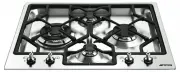
PGA64
gas cooktop
"Loading the manual" means you need to wait until the file loads and becomes available for online reading. Some manuals are very large, and the time they take to appear depends on your internet speed.
Was this manual helpful?
About this manual
- Brand
- Smeg
- Model
- PGA64
- Document type
- User Manual
- Category
- Hob
- Language(s)
- English
- Pages
- 19
- File size
- 1.1 MB
- Format
Other Manuals for Smeg PGA64
Summary
21 Contents THESE INSTRUCTIONS ARE VALID ONLY FOR THE DESTINATION COUNTRIES WHOSE IDENTIFYING SYMBOLS ARE INCLUDED ON THE COVER OF THIS MAN-UAL. INSTRUCTIONS FOR THE USER: these instructions contain userrecommendations, a description of the controls and the correctprocedures for cleaning and mainten...
General instructions 22 1. INSTRUCTIONS FOR USE THIS MANUAL CONSTITUTES AN INTEGRAL PART OF THE APPLIANCE. THISMANUAL CONSTITUTES AN INTEGRAL PART OF THE APPLIANCE. IT SHOULD BEKEPT INTACT AND AT HAND FOR THE APPLIANCE’S ENTIRE LIFE CYCLE.IT IS IMPORTANT TO CAREFULLY READ THIS MANUAL AND ALL THEINST...
General instructions 24 2. SAFETY PRECAUTIONS REFER TO THE INSTALLATION INSTRUCTIONS FOR THE SAFETY REGULATIONSFOR ELECTRIC OR GAS APPLIANCES AND VENTILATION FUNCTIONS.IN YOUR INTERESTS AND FOR YOUR SAFETY THE LAW REQUIRES THAT THEINSTALLATION AND SERVICING OF ALL ELECTRICAL APPLIANCES IS CARRIEDOUT...
Ask a question
Related manuals
Popular Smeg Hobs
More Smeg Hobs models
 Smeg SIM1964DG User Manual
 Smeg HOBD182DG User Manual
 Smeg HOBD682D1 User Manual
 Smeg P64 User Manual
 Smeg P75 User Manual
 Smeg PGA75-4 User Manual
 Smeg PGA95-4 User Manual
 Smeg PGA96 User Manual
 Smeg PGF30T-1 User Manual
 Smeg PSA906-5 User Manual
 Smeg PV395LCNAU User Manual
 Smeg PX364LAU User Manual
 Smeg SAI95 User Manual
 Smeg SAI4634D User Manual