Smeg PV175CB - User Manual

Smeg PV175CB – User Manual, read for free online in PDF format. We hope this helps you resolve any issues you may have. If you have further questions, please contact us through the contact form.


Table of Contents:
- Page 2 – Instructions; General safety instructions; Risk of personal injury
- Page 3 – Manufacturer liability; Power voltage
- Page 4 – Identification plate
- Page 5 – Description; General Description
- Page 6 – Cooking zones; Available accessories
- Page 7 – Use; Improper use
- Page 8 – and wait 60 seconds before trying
- Page 9 – Practical tips for using the hob
- Page 10 – Cleaning and maintenance; Cleaning the appliance; Ordinary daily cleaning
- Page 11 – Cooking hob grids
- Page 12 – Installation; Safety instructions; mm
- Page 13 – Over empty kitchen unit or drawers
- Page 14 – Hob seal
- Page 15 – Connection to LPG
- Page 16 – Extraction of the combustion products; Adaptation to different types of
- Page 17 – Removing the hob top
- Page 18 – Replacing nozzles
- Page 19 – Adjusting the minimum setting for LPG
- Page 20 – Gas types and Countries
- Page 21 – Burner and nozzle characteristics tables
- Page 22 – Electrical connection; General information
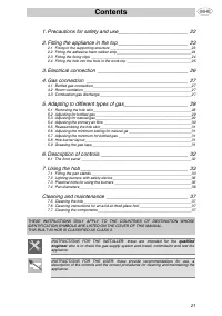
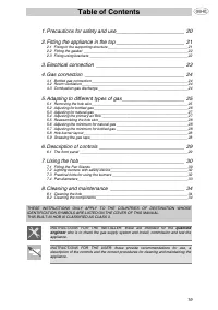
Contents
25
EN
1 Instructions
26
1.1 General safety instructions
26
1.2 Manufacturer liability
27
1.3 Appliance purpose
27
1.4 Disposal
27
1.5 Identification plate
28
1.6 This user manual
28
1.7 How to read the user manual
28
2 Description
29
2.1 General Description
29
2.2 Symbols
30
2.3 Available accessories
30
3 Use
31
3.1 Instructions
31
3.2 First use
31
3.3 Using the hob
32
4 Cleaning and maintenance
34
4.1 Instructions
34
4.2 Cleaning the appliance
34
5 Installation
36
5.1 Safety instructions
36
5.2 Section cut from the work surface
36
5.3 Mounting
37
5.4 Fixing brackets
38
5.5 Gas connection
38
5.6 Adaptation to different types of gas
40
5.7 Electrical connection
46
We advise you to read this manual carefully, which contains all the instructions for
maintaining the appliance's aesthetic and functional qualities.
For further information on the product: www.smeg.com
These instructions apply only for the destination countries listed on the appliance's data plate.
This is a class 3 built in hob.
"Loading the manual" means you need to wait until the file loads and becomes available for online reading. Some manuals are very large, and the time they take to appear depends on your internet speed.
Was this manual helpful?
About this manual
- Brand
- Smeg
- Model
- PV175CB
- Document type
- User Manual
- Language(s)
- English
- Pages
- 22
- File size
- 571.5 KB
- Format
Summary
Instructions 26 1 Instructions 1.1 General safety instructions Risk of personal injury • During use the appliance and its accessible parts become very hot. • Never touch the heating elements during use. • Keep children under eight years of age at a safe distance if they are not constantly supervised...
Instructions 27 EN 1.2 Manufacturer liability The manufacturer declines all liability for damage to persons or property caused by:• use of the appliance other than the one envisaged, • non-observance of the user manual provisions, • tampering with any part of the appliance, • use of non-original spa...
Instructions 28 1.5 Identification plate The identification plate bears the technical data, serial number and brand name of the appliance. Do not remove the identification plate for any reason. 1.6 This user manual This user manual is an integral part of the appliance and must therefore be kept in i...