Page 2 - “THIS APPLIANCE SHALL BE INSTALLED IN ACCORDANCE WITH THE
2 Dear user, Our objective is to make this product provide you with the best output which is manufactured in our modern facilities in a careful working environment, in compliance with total quality concept. Therefore, we suggest you to read the user manual carefully before using the product and, kee...
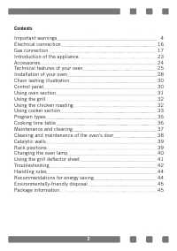
Page 3 - Contents; Using the grill deflector sheet
3 Contents Important warnings 4 Electrical connection 16 Gas connection 17 Introduction of the appliance 23 Accessories 24 Technical features of your oven 25 Installation of your oven 28 Chain lashing illustration 30 Control panel 30 Using oven section 31 Using the grill 32 Using the chicken roastin...
Page 5 - the appliance. Do not put ignitable or flammable materials
5 13. NEVER try to put out the fire with water. Only shut down the device circuit and then cover the flame with a cover or a fire blanket. 14. Children under 8 years of age should be kept away, if they cannot be monitored continuously. 15. Touching the heating elements should be avoided. 16. CAUTION...
Page 6 - and/or under influence of alcohol which may affect your
6 23. The appliance is not suitable for use with an external timer or a separate remote control system. 24. Do not heat closed cans and glass jars. The pressure may lead jars to explode. 25. Oven handle is not a towel drier. Do not hang towels, etc. on the oven handle. 26. Do not place the oven tray...
Page 10 - or its service agent or an equally qualified personnel to; device circuit is open before changing the lamp.
10 Electrical Safety1. Plug the appliance in a grounded socket protected by a fuse conforming to the values specified in the technical specifications chart. 2. Have an authorized electrician set grounding equipment. Our company shall not be responsible for the damages that shall be incurred due to u...
Page 11 - type ‘’Y’’
11 11. Make sure that there is no liquid or humidity in the outlet where the product plug is installed. 12. The rear surface of the oven also heats up when the oven is operated. Electrical connections shall not touch the rear surface, otherwise the connections may be damaged. 13. Do not tighten the ...
Page 12 - shall be connected to fixed power supply according to
12 20. Fixed connections shall be connected to a power supply enabling omnipolar disconnection. For appliances with over voltage category below III, disconnection device shall be connected to fixed power supply according to wiring code. Gas Safety1. This appliance is not connected to burning product...
Page 15 - required for the operation of this product as defined is
15 Intended Use 1. This product is designed for home use. Commercial use of the appliance is not permitted. 2. This appliance may only be used for cooking purposes. It shall not be used for other purposes like heating a room. 3. This appliance shall not be used to heat plates under the grill, drying...
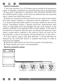
Page 16 - Electrical connection scheme
16 Electrical Connection1. Your oven requires 16 or 32 Ampere fuse according to the appliance’s power. If necessary, installation by a qualified electrician is recommended. 2. Your oven is adjusted in compliance with 220-240V AC/380-415V AC 50/60Hz.electric supply. If the mains are different from th...
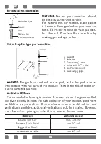
Page 18 - The gas hose must not be clamped, bent ar trapped or come; Ventilation Of Room; Room Size; Smaller than 5 m3; Natural gas connection should; rn; outlet
18 For natural gas connection; United kingdom type gas connection: WARNING: The gas hose must not be clamped, bent ar trapped or come into contact with hat parts of the product. There is the risk of explosion due to damaged gas hose. Ventilation Of Room The air needed for burning is received from ro...
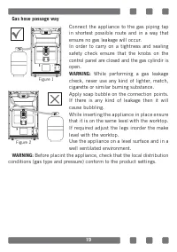
Page 19 - Gas hose passage way; While performing a gas leakage; Figure 1
19 Gas hose passage way Connect the appliance to the gas piping tap in shortest possible route and in a way that ensure no gas leakage will occur.In order to carry on a tightness and sealing safety check ensure that the knobs on the control panel are closed and the gas cylindir is open. WARNING: Whi...
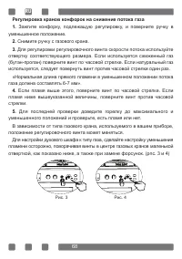
Page 20 - Reduced gas flow rate setting for hob taps; positions and check whether the flame is on or off.; Figure 3
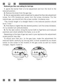
20 Reduced gas flow rate setting for hob taps 1. Ignite the burner that is to be adjustment and turn the knob to the reduced position. 2. Remove the knob from the gas tap. 3. Use an appropriately sized screwdriver to adjust the flow rate adjustment screw. For LPG (butane-pro pane) turn the screw clo...
Page 22 - The Gas Oven
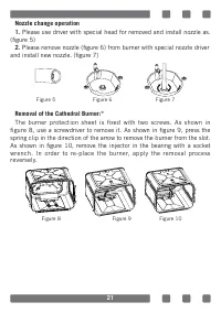
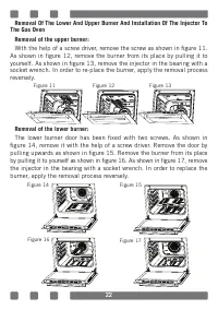
22 Removal Of The Lower And Upper Burner And Installation Of The Injector To The Gas Oven Removal of the upper burner:With the help of a screw driver, remove the screw as shown in figure 11. As shown in figure 12, remove the burner from its place by pulling it to yourself. As shown in figure 13, rem...
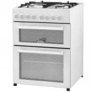
Page 23 - INTRODUCTION OF THE APPLIANCE
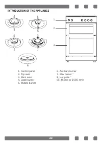
23 INTRODUCTION OF THE APPLIANCE 1 2 3 1. Control panel2. Top oven3. Main oven4. Large burner5. Middle burner 6. Auxiliary burner7. Wok burner *8. Hot plate * (Ø145 mm or Ø185 mm) 6 5 4 7 8
Page 24 - Accesories
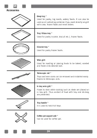
24 Accesories Coffee pot support unit * Can be used for coffee pot. Deep tray * Used for pastry, big roasts, watery foods. It can also be used as oil collecting container if you roast directly on grill with cake, frozen foods and meat dishes. Tray / Glass tray * Used for pastry (cookie, biscuit etc....
Page 25 - Technical Features Of Your Oven; any problems rising because of any faulty modification.; WARNING; : The values provided with the appliance or its accompanying
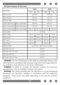
25 Technical Features Of Your Oven Specification 50x60 60x60 Main Top Main Top Outside width 500 mm 600 mm Outside depth 630 mm 630 mm Outside height 900 mm 900 mm Lower inside width Upper inside width 360 mm 460 mm Lower inside depth Upper inside depth 400 mm 400 mm Lower inside height Upper inside...
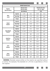
Page 27 - a comma. For example The diameter of 1,70 mm is specified as 170 on
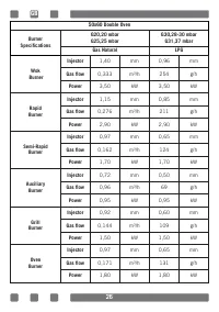
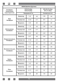
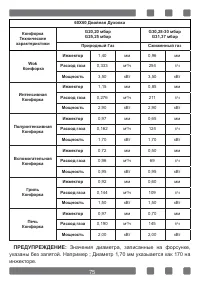
27 60x60 Double Oven Burner Specifications G20,20 mbarG25,25 mbar G30,28-30 mbar G31,37 mbar Gas Natural LPG Wok urner Injector 1,40 mm 0,96 mm Gas flow 0,333 m³/h 254 g/h Power 3,50 kW 3,50 kW Rapid Burner Injector 1,15 mm 0,85 mm Gas flow 0,276 m³/h 211 g/h Power 2,90 kW 2,90 kW Semi-Rapid Burner ...
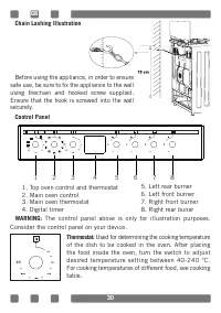
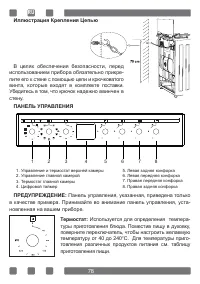
Page 30 - Chain Lashing Illustration; Before using the appliance, in order to ensure; Control Panel; The control panel above is only for illustration purposes.
30 Chain Lashing Illustration Before using the appliance, in order to ensure safe use, be sure to fix the appliance to the wall using thechain and hooked screw supplied. Ensure that the hook is screwed into the wall securely. Control Panel WARNING: The control panel above is only for illustration pu...
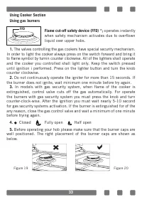
Page 33 - In models with gas security system, when flame of the cooker is; Closed; FFD
33 Using Cooker SectionUsing gas burners Flame cut-off safety device (FFD) *; operates instantly when safety mechanism activates due to overflown liquid over upper hobs. 1. The valves controlling the gas cookers have special security mechanism. In order to light the cooker always press on the switch...
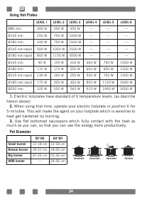
Page 34 - much as you can, so that you can use the energy more productively.; Pot Diameter
34 Using Hot Plates LEVEL 1 LEVEL 2 LEVEL 3 LEVEL 4 LEVEL 5 LEVEL 6 Ø80 mm 200 W 250 W 450 W --- --- --- Ø145 mm 250 W 750 W 1000 W --- --- --- Ø180 mm 500 W 750 W 1500 W --- --- --- Ø145 mm rapid 500 W 1000 W 1500 W --- --- --- Ø180 mm rapid 850 W 1150 W 2000 W --- --- --- Ø145 mm 95 W 155 W 250 W ...
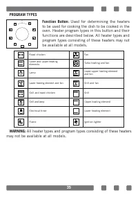
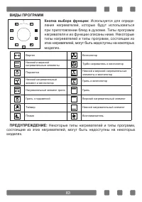
Page 35 - PROGRAM TYPES; All heater types and program types consisting of these heaters
35 PROGRAM TYPES WARNING: All heater types and program types consisting of these heaters may not be available at all models. 0 Function Button: Used for determining the heaters to be used for cooking the dish to be cooked in the oven. Heater program types in this button and their functions are descr...
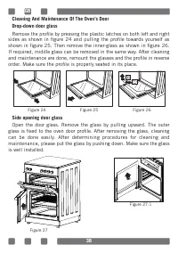
Page 38 - Side opening door glass; Open the door glass. Remove the glass by pulling upward. The outer
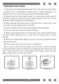
38 Cleaning And Maintenance Of The Oven’s Door Drop-down door glassRemove the profile by pressing the plastic latches on both left and right sides as shown in figure 24 and pulling the profile towards yourself as shown in figure 25. Then remove the inner-glass as shown in figure 26. If required, mid...
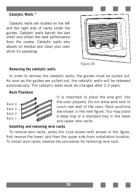
Page 39 - Catalytic walls are located on the left; Removing the catalytic walls; are shown in the next figure. You may place
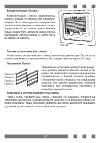
39 Catalytic Walls * Catalytic walls are located on the left and the right side of cavity under the guides. Catalytic walls banish the bad smell and obtain the best performance from the cooker. Catalytic walls also absorb oil residue and clean your oven while it’s operating. Removing the catalytic w...
Page 40 - Type G9 Lamp
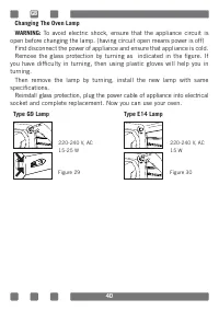
40 Changing The Oven LampWARNING: To avoid electric shock, ensure that the appliance circuit is open before changing the lamp. (having circuit open means power is off) First disconnect the power of appliance and ensure that appliance is cold. Remove the glass protection by turning as indicated in th...
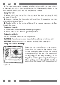
Page 41 - Using The Grill Deflector Sheet *; when the oven is in Grill mode (figure 31); case the grill deflector sheet will be unnecessary.
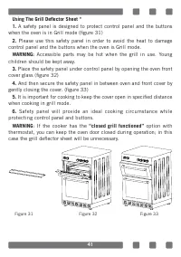
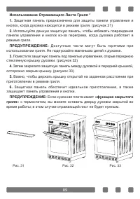
41 Using The Grill Deflector Sheet * 1. A safety panel is designed to protect control panel and the buttons when the oven is in Grill mode (figure 31) 2. Please use this safety panel in order to avoid the heat to damage control panel and the buttons when the oven is Grill mode. WARNING: Accessible p...
Page 42 - TROUBLESHOOTING; You may solve the problems you may encounter with your product by
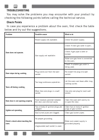
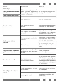
42 TROUBLESHOOTING You may solve the problems you may encounter with your product by checking the following points before calling the technical service. Check PointsIn case you experience a problem about the oven, first check the table below and try out the suggestions. Problem Possible cause What t...
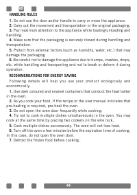
Page 44 - RECOMMENDATIONS FOR ENERGY SAVING
44 HANDLING RULES1. Do not use the door and/or handle to carry or move the appliance. 2. Carry out the movement and transportation in the original packaging. 3. Pay maximum attention to the appliance while loading/unloading and handling. 4. Make sure that the packaging is securely closed during hand...
Page 46 - УВАЖАЕМЫЙ ПОКУПАТЕЛЬ!; Благодарим Вас за то, что отдали предпочтение; ПРИМЕЧАНИЕ
УВАЖАЕМЫЙ ПОКУПАТЕЛЬ! Благодарим Вас за то, что отдали предпочтение нашей бытовой технике . Надеемся, что Вам понравится продукция нашей компании, и в будущем Вы отдадите ей предпочтение . Данное изделие произведено на современном оборудовании без нанесения вреда окружающей среде. Соответствует треб...
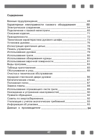
Page 47 - Содержание; пе; Характерные
47 Содержание Важные прудупреждения 48 Электрическое соединение 6 4 Подключение к газовой магистрали 6 5 Описание изделия 71 Принадлежности 7 2 Технические характеристики духового шкафа 7 3 Установка духовки 7 6 Иллюстрация крепления цепью 7 8 Панель управления 7 8 Использование духовки 7 9 Использо...
Page 57 - типа «Y»
57 16. Убедитесь, что штепсельная вилка плотно вставлена в розетку, чтобы избежать образования искр. 17. Не используйте пароочистители при очистке прибора, в противном случае может возникать поражение электрическим током. 18. Для установки требуется многополючный переключатель, способный отключать и...
Page 58 - Газобезопасность
58 Газобезопасность 1. Данный прибор не подключается к установке удаления продуктов горения. Данный прибор дол - жен быть подключен и установлен в соответствии с действующими правилами установки. Особенно следует учитывать условия, касающиеся вентиляции. 2. Когда используется газовая плита, влажност...
Page 61 - Нельзя тушить воспламенившееся масло или жир
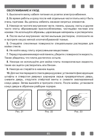
■ Периодически (не реже одного раза в полгода) проверяйте состояние кабеля электропитания и гибкого шланга подвода газа. При обнаружении каких-либо дефектов (трещины, следы оплавлений) немедленно обратитесь в сервисную службу. Гибкий шланг подвода газа заменяется только персоналом специали- зированн...
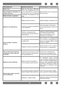
Page 62 - Таблица возможных неисправностей и меры
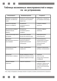
Таблица возможных неисправностей и меры по их устранению. Что произошло? Возможная причина Что делать? Конфорки не зажигаются. Неровное, нестабильное пламя. Неровность пламени вызвано неправильной настройкой подачи газа. Обратитесь к специалисту для проверки газопровода. Внезапные перепады пламени в...
Page 64 - Схема электрического соединения
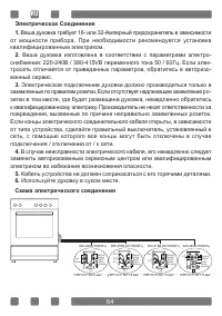
Электрическое Соединение1. Ваша духовка требует 16- или 32-Амперный предохранитель в зависимости от мощности прибора. При необходимости рекомендуется установка квалифицированным электриком. 2. Ваша духовка изготовлена в соответствии с параметрами электро - снабжения: 220-240В / 380-415VВ переменного...
Page 65 - Для подключения к баллону сжиженного газа
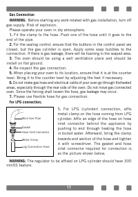
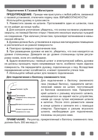
Подключение К Газовой МагистралиПРЕДУПРЕЖДЕНИЕ: Прежде чем приступать к любой работе, связанной с газовой установкой, отключите подачу газа. ВЗРЫВООПАСНОСТЬ! Используйте духовку в сухом месте. 1. Разместите зажим на шланге. Проталкивайте один из шлангов, пока он не дойдет до конца трубы. 2. Для конт...
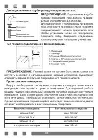
Page 66 - Величина помещения; не требуется
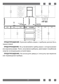
Для подключения к трубопроводу натурального газа; ПРЕДУПРЕЖДЕНИЕ: Подключение к трубо - проводу природного газа должно произво - диться уполномоченной службой. Для подключения к трубопроводу природного газа, установите прокладку к гайке на кромке соединительного шланга природного газа. Чтобы установ...
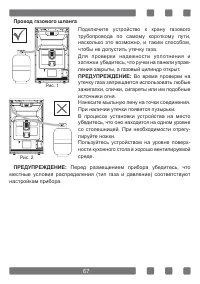
Page 67 - Проход газового шланга
Проход газового шланга Подключите устройство к крану газового трубопровода по самому короткому пути, насколько это возможно, и таким способом, чтобы не допустить утечку газа. Для проверки надежности уплотнения и затяжки убедитесь, что ручки на панели управ - ления закрыты, а газовый цилиндр открыт. ...
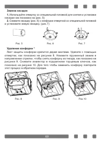
Page 70 - на рис.12 снимите горелку с гнезда потянув ее на себя.; Снятие нижней горелки:; Крышка нижней горелки зафиксирована с помощью двух винтов, отсое
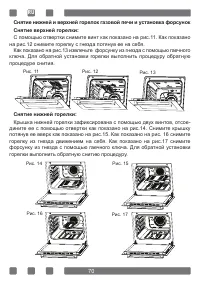
RU Снятие нижней и верхней горелок газовой печи и установка форсунок Снятие верхней горелки: С помощью отвертки снимите винт как показано на рис.11. Как показано на рис.12 снимите горелку с гнезда потянув ее на себя. Как показано на рис.13 извлечьте форсунку из гнезда с помощью гаечного ключа. Для о...
Page 71 - ОПИСАНИЕ ИЗДЕЛИЯ; Стандартная конфорка
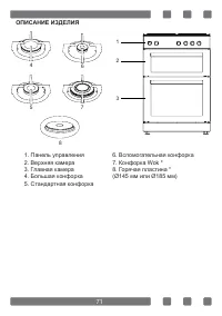
ОПИСАНИЕ ИЗДЕЛИЯ 1 2 3 1. Панель управления 2. Верхняя камера 3. Главная камера 4. Большая конфорка 5. Стандартная конфорка 6. Вспомогательная конфорка 7. Конфорка Wok * 8. Горячая пластина * (Ø145 мм или Ø185 мм) 6 5 4 7 8 71
Page 72 - Принадлежности
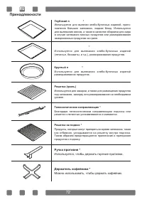
Принадлежности Держатель кофейника * Можно использовать, чтобы держать кофейник. Глубокий п ɪɨɬɢɜɟɧɶ * Используется для выпечки хлебо-булочных изделий, приго - товления больших запеканок, жидких блюд. Используется для выпекания кексов, а также в качестве сборника для жира в случае запекания мясных п...
Page 73 - Технические Характеристики Духового Шкафа; ПРЕДУПРЕЖДЕНИЕ
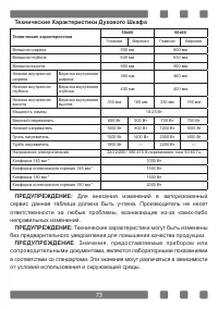
Технические Характеристики Духового Шкафа Технические характеристики 50x60 60x60 Главная Верхняя Главная Верхняя Внешняя ширина 500 мм 600 мм Внешняя глубина 630 мм 630 мм Внешняя высота 900 мм 900 мм Нижняя внутренняя ширина Верхняя внутренняя ширина 360 мм 460 мм Нижняя внутренняя глубина Верхняя ...
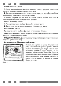
Page 80 - Использование Обжаривания Курицы *
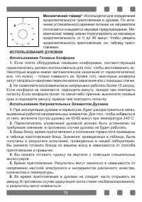
Использование Гриля1. Когда вы помещаете гриль на верхнюю полку, продукты питания на гриле не должны соприкасаться с решеткой. 2. Вы можете предварительно разогревать гриль в течение 5 минут. Если необходимо, вы можете перевернуть пищу. 3. Пища должна находиться в центре гриля, чтобы обеспечить макс...
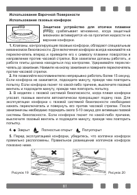
Page 81 - Защитное устройство для отсечки пламени
Использование Варочной ПоверхностиИспользование газовых конфорок Защитное устройство для отсечки пламени (FFD); срабатывает мгновенно, когда защитный механизм активируется из-за пролития жидкости на верхние конфорки. 1. Клапаны, контролирующие газовые конфорки, обладают специальным механизмом безопа...
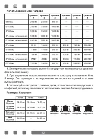
Page 82 - Использование Зон Нагрева; При первичном использовании включите конфорку в положении 6 на; Размеры Кастрюли
Использование Зон Нагрева Уровень 1 Уровень 2 Уровень 3 Уровень 4 Уровень 5 Уровень 6 Ø80 мм 200 Вт 250 Вт 450 Вт ---- ---- ---- Ø145 мм 250 Вт 750 Вт 1000 Вт ---- ---- ---- Ø180 мм 500 Вт 750 Вт 1500 Вт ---- ---- ---- Ø145 мм интенсивная 500 Вт 1000 Вт 1500 Вт ---- ---- ---- Ø180 мм интенсивная 850...
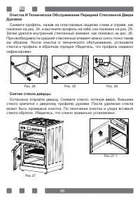
Page 86 - Снимите профиль, нажав на пластиковые защелки слева и справа, как; Снятие стекла дверцы; Осторожно откройте дверцу. Снимите стекло, потянув вверх. Внешнее
Очистка И Техническое Обслуживание Передней Стеклянной Двери Духовки Снимите профиль, нажав на пластиковые защелки слева и справа, как показано на рис. 24, и вытяните профиль на себя, как показано на рис. 25. Затем удалите внутренний стеклянный элемент, как показано на рис. 26. При необходимости сре...
Page 88 - Тип G9 Лампы
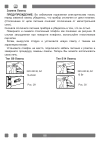
Замена ЛампыПРЕДУПРЕЖДЕНИЕ: Во избежание поражения электрическим током, перед заменой лампы убедитесь, что прибор отключен от цепи питания. (Отключение от цепи питание означает отключение от магистральной сети). Сначала отключите питание прибора и убедитесь в том, что он остыл. Поверните и снимите с...
Page 90 - ниже и попробуйте устранить неполадку, выполнив рекомендации.
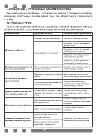
НАХОЖДЕНИЕ И УСТРАНЕНИЕ НЕИСПРАВНОСТЕЙ Вы можете решить проблемы, с которыми вы можете столкнуться в приборе, проверив следующие пункты перед тем, как обратиться в техническую службу. Контрольные точки Если у вас возникла проблема с духовкой, сначала проверьте таблицу ниже и попробуйте устранить неп...
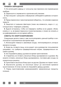
Page 92 - СОВЕТЫ ПО ЭНЕРГОСБЕРЕЖЕНИЮ
ПРАВИЛА ОБРАЩЕНИЯ1. Не используйте дверцу и / или ручку при переносе или перемещении прибора. 2. Переносите и перевозите в оригинальной упаковке. 3. При погрузке / разгрузке и обращении соблюдайте крайнюю осторож - ность. 4. Перед переносом и транспортировкой убедитесь, что упаковка надежно закрыта....
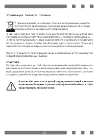
Page 93 - п у н к т с б о р а д л я; УПАКОВКА; Утилизация
1. Данное изделие не содержит опасных и запрещенных веществ.Соответствует требованиям положений Директивы ЕС об отходах электрического и электронного оборудования 2 . Д а н н о е и з д е л и е п р о и з в е д е н о и з в ы с о к о к а ч е с т в е н н ы х д е т а л е й и материалов, которые могут быт...