Page 2 - “THIS APPLIANCE SHALL BE INSTALLED IN ACCORDANCE WITH THE
2 Dear user, Our objective is to make this product provide you with the best output which is manufactured in our modern facilities in a careful working environment, in compliance with total quality concept. Therefore, we suggest you to read the user manual carefully before using the product and, kee...
Page 3 - Contents
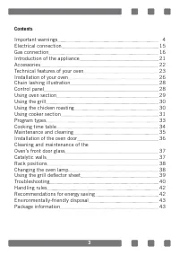
3 Contents Important warnings 4 Electrical connection 15 Gas connection 16 Introduction of the appliance 21 Accessories 22 Technical features of your oven 23 Installation of your oven 26 Chain lashing illustration 28 Control panel 28 Using oven section 29 Using the grill 30 Using the chicken roastin...
Page 5 - Cooking process shall always be supervised.
5 13. NEVER try to put out the fire with water. Only shut down the device circuit and then cover the flame with a cover or a fire blanket. 14. Children under 8 years of age should be kept away, if they cannot be monitored continuously. 15. Touching the heating elements should be avoided. 16. CAUTION...
Page 9 - WARNING: Don’t use oven and grill burners at same
9 54. To prevent overheating, the appliance should not be installed behind of a decorative cover. 55. Turn off the appliance before removing the safeguards. After cleaning, install the safeguards according to instructions. 56. Cable fixing point shall be protected. 57. WARNING: Don’t use oven and gr...
Page 11 - type ‘’Y’’
11 15. If the power supply cable is damaged, it must be replaced by its manufacturer or authorized technical service or any other personnel qualified at the same level, in order to avoid any dangerous situation. 16. Make sure the plug is inserted firmly into wall socket to avoid sparks. 17. Do not u...
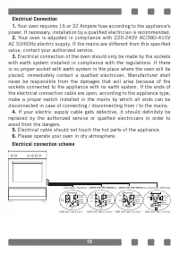
Page 15 - Electrical connection scheme
15 Electrical Connection1. Your oven requires 16 or 32 Ampere fuse according to the appliance’s power. If necessary, installation by a qualified electrician is recommended. 2. Your oven is adjusted in compliance with 220-240V AC/380-415V AC 50/60Hz.electric supply. If the mains are different from th...
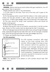
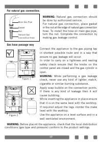
Page 17 - For natural gas connection; Natural gas connection should; Gas hose passage way; While performing a gas leakage; Figure 1
17 For natural gas connection; WARNING: Natural gas connection should be done by authorized service. For natural gas connection, place gasket in the nut at the edge of natural gas connection hose. To install the hose on main gas pipe, turn the nut. Complete the connection by making gas leakage contr...
Page 18 - Ventilation of room; Room size
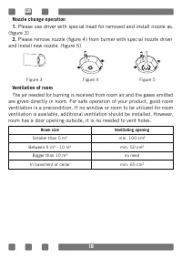
18 Nozzle change operation1. Please use driver with special head for removed and install nozzle as. (figure 3) 2. Please remove nozzle (figure 4) from burner with special nozzle driver and install new nozzle. (figure 5) Ventilation of room The air needed for burning is received from room air and the...
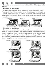
Page 20 - With the help of a screw driver, remove the screw as shown in figure 8.; Removal of the lower burner:; The lower burner door has been fixed with two screws. As shown in; Figure 8
20 Removal of the lower and upper burner and installation of the injector to the gas oven Removal of the upper burner: With the help of a screw driver, remove the screw as shown in figure 8. As shown in figure 9, remove the burner from its place by pulling it to yourself. As shown in figure 10, remo...
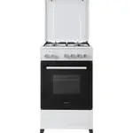
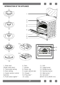
Page 21 - INTRODUCTION OF THE APPLIANCE
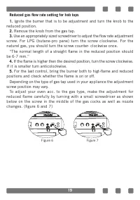
21 1. Glass door(Sheet metal door)2. Thermostat setting3. Oven setting4. Cooker section control Switches5. Push button lighter * 6. Door7. Handle8. Plastic leg9. Lower cabinet door9.1 Drawer *9.2 Flap door *10. Lamp 11. Grill12. Large burner13. Middle burner14. Auxiliary burner15. Wok burner *16. Ho...
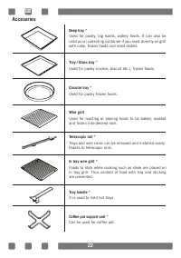
Page 22 - Accesories
22 Accesories Coffee pot support unit * Can be used for coffee pot. Deep tray * Used for pastry, big roasts, watery foods. It can also be used as oil collecting container if you roast directly on grill with cake, frozen foods and meat dishes. Tray / Glass tray * Used for pastry (cookie, biscuit etc....
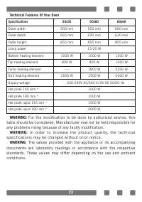
Page 23 - Technical Features Of Your Oven; Specifications; For the modification to be done by authorized service, this; WARNING; : The values provided with the appliance or its accompanying
23 Technical Features Of Your Oven Specifications 50x55 50x60 60x60 Outer width 500 mm 500 mm 600 mm Outer depth 565 mm 630 mm 630 mm Outer height 855 mm 855 mm 855 mm Lamp power 15-25 W Bottom heating element 1000 W 1000 W 1200 W Top heating element 800 W 800 W 1000 W Turbo heating element ----- 18...
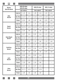
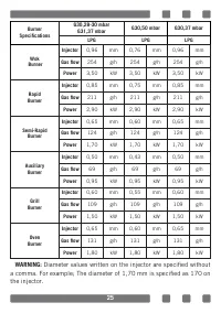
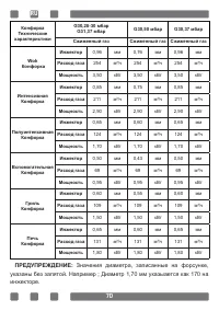
Page 25 - Diameter values written on the injector are specified without
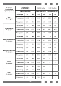
25 Burner Specifications G30,28-30 mbar G31,37 mbar G30,50 mbar G30,37 mbar LPG LPG LPG Wok Burner Injector 0,96 mm 0,76 mm 0,96 mm Gas flow 254 g/h 254 g/h 254 g/h Power 3,50 kW 3,50 kW 3,50 kW Rapid Burner Injector 0,85 mm 0,75 mm 0,85 mm Gas flow 211 g/h 211 g/h 211 g/h Power 2,90 kW 2,90 kW 2,90...
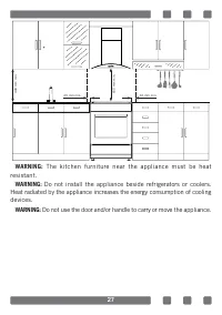
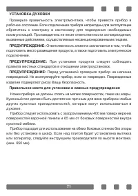
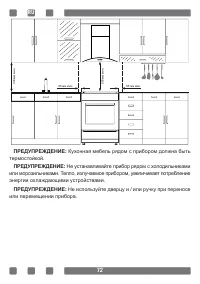
Page 26 - INSTALLATION OF YOUR OVEN; It is customer's responsibility to prepare the location the; Right Place For Installation And Important Warnings; Appliance should be used with a clearance of minimum 400 mm over
26 INSTALLATION OF YOUR OVEN Check if the electrical installation is proper to bring the appliance in operating condition. If electricity installation is not suitable, call an electrician and plumber to arrange the utilities as necessary. Manufacturer shall not be held responsible for damages caused...
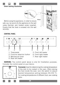
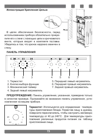
Page 28 - Chain lashing illustration; Before using the appliance, in order to ensure; CONTROL PANEL; The control panel above is only for illustration purposes.
28 Chain lashing illustration Before using the appliance, in order to ensure safe use, be sure to fix the appliance to the wall using thechain and hooked screw supplied. Ensure that the hook is screwed into the wall securely. CONTROL PANEL WARNING: The control panel above is only for illustration pu...
Page 31 - FFD
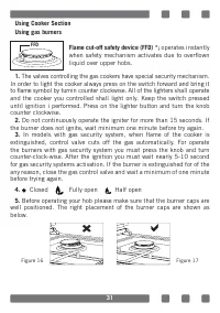
31 Using Cooker SectionUsing gas burners Flame cut-off safety device (FFD) *; operates instantly when safety mechanism activates due to overflown liquid over upper hobs. 1. The valves controlling the gas cookers have special security mechanism. In order to light the cooker always press on the switch...
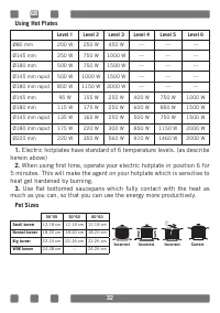
Page 32 - Using Hot Plates; Use flat bottomed saucepans which fully contact with the heat as; Pot Sizes
32 Using Hot Plates Level 1 Level 2 Level 3 Level 4 Level 5 Level 6 Ø80 mm 200 W 250 W 450 W --- --- --- Ø145 mm 250 W 750 W 1000 W --- --- --- Ø180 mm 500 W 750 W 1500 W --- --- --- Ø145 mm rapid 500 W 1000 W 1500 W --- --- --- Ø180 mm rapid 850 W 1150 W 2000 W --- --- --- Ø145 mm 95 W 155 W 250 W ...
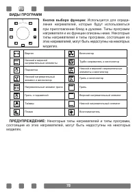
Page 33 - PROGRAM TYPES; All heater types and program types consisting of these heaters
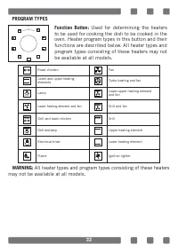
33 PROGRAM TYPES WARNING: All heater types and program types consisting of these heaters may not be available at all models. 0 Function Button: Used for determining the heaters to be used for cooking the dish to be cooked in the oven. Heater program types in this button and their functions are descr...
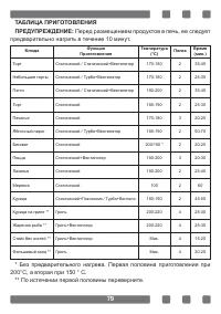
Page 34 - Oven must be preheated for 10 minutes before placing the; * Without pre-heating. Half of the cooking should be 200°C and then
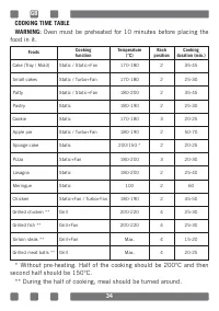
34 COOKING TIME TABLEWARNING: Oven must be preheated for 10 minutes before placing the food in it. Foods Cooking function Temperature (°C) Rack position Cooking duration (min.) Cake (Tray / Mold) Static / Static+Fan 170-180 2 35-45 Small cakes Static / Turbo+Fan 170-180 2 25-30 Patty Static / Static...
Page 36 - Installation Of The Oven Door
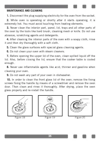
36 Installation Of The Oven Door Completely open the oven door by pulling it to yourself. After wards, perform the unlocking process by pulling the hinge lock upwards with the help of a screw driver as shown in figure 21.1. Bring the hinge lock to the widest angle as shown in figure 21.2 . Bring bot...
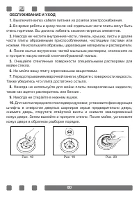
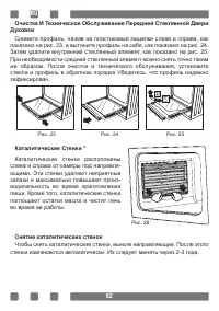
Page 37 - Cleaning And Maintenance Of The Oven’s Front Door Glass; Catalytic walls are located on the left; Removing the catalytic walls
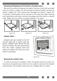
37 Cleaning And Maintenance Of The Oven’s Front Door Glass Remove the profile by pressing the plastic latches on both left and right sides as shown in figure 23 and pulling the profile towards yourself as shown in figure 24. Then remove the inner-glass as shown in figure 25. If required, middle glas...
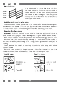
Page 38 - To avoid electric shock, ensure that the appliance circuit is; Type G9 Lamp
38 Rack Positions It is important to place the wire grill into the oven properly. Do not allow wire rack to touch rear wall of the oven. Rack positions are shown in the next figure. You may place a deep tray or a standard tray in the lower and upper wire racks. Installing and removing wire racks To ...
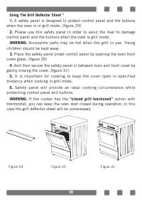
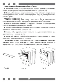
Page 39 - “closed grill functioned”
39 Using The Grill Deflector Sheet *1. A safety panel is designed to protect control panel and the buttons when the oven is in grill mode. (figure 29) 2. Please use this safety panel in order to avoid the heat to damage control panel and the buttons when the oven is grill mode. WARNING: Accessible p...
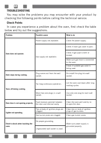
Page 40 - TROUBLESHOOTING; You may solve the problems you may encounter with your product by; Check Points; below and try out the suggestions.
40 TROUBLESHOOTING You may solve the problems you may encounter with your product by checking the following points before calling the technical service. Check Points In case you experience a problem about the oven, first check the table below and try out the suggestions. Problem Possible cause What ...
Page 42 - RECOMMENDATIONS FOR ENERGY SAVING
42 HANDLING RULES1. Do not use the door and/or handle to carry or move the appliance. 2. Carry out the movement and transportation in the original packaging. 3. Pay maximum attention to the appliance while loading/unloading and handling. 4. Make sure that the packaging is securely closed during hand...
Page 44 - Уважаемый покупатель,; Мы стремимся обеспечить вам максимальную производительность с; «ДАННОЕ ИЗДЕЛИЕ СЛЕДУЕТ УСТАНОВИТЬ В СООТВЕТСТВИИ С; «Соответствует требованиям положений
44 Уважаемый покупатель, Мы стремимся обеспечить вам максимальную производительность с помощью данного продукта, который изготовлен на наших современных производственных предприятиях в условиях тщательной рабочей среды в соответствии с концепцией всеобщего контроля качества. Поэтому мы рекомендуем в...
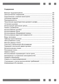
Page 45 - Содержание
45 Содержание Важные прудупреждения 46 Электрическое соединение 60 Подключение к газовой магистрали 61 Описание изделия 66 Принадлежности 67 Технические характеристики духового шкафа 68 Установка духовки 70 Иллюстрация крепления цепью 73 Панель управления 73 Использование духовки 74 Использование гр...
Page 55 - типа «Y»
55 16. Убедитесь, что штепсельная вилка плотно вставлена в розетку, чтобы избежать образования искр. 17. Не используйте пароочистители при очистке прибора, в противном случае может возникать поражение электрическим током. 18. Для установки требуется многополючный переключатель, способный отключать и...
Page 56 - Газобезопасность
56 Газобезопасность 1. Данный прибор не подключается к установке удаления продуктов горения. Данный прибор дол- жен быть подключен и установлен в соответствии с действующими правилами установки. Особенно следует учитывать условия, касающиеся вентиляции. 2. Когда используется газовая плита, влажность...
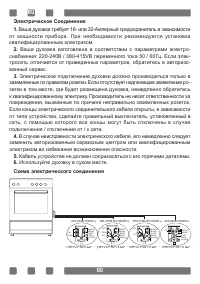
Page 60 - Схема электрического соединения
60 Электрическое Соединение1. Ваша духовка требует 16- или 32-Амперный предохранитель в зависимости от мощности прибора. При необходимости рекомендуется установка квалифицированным электриком. 2. Ваша духовка изготовлена в соответствии с параметрами электро- снабжения: 220-240В / 380-415VВ переменно...
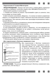
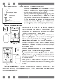
Page 61 - Для подключения к баллону сжиженного газа
61 Подключение К Газовой МагистралиПРЕДУПРЕЖДЕНИЕ: Прежде чем приступать к любой работе, связанной с газовой установкой, отключите подачу газа. ВЗРЫВООПАСНОСТЬ! Используйте духовку в сухом месте. 1. Разместите зажим на шланге. Проталкивайте один из шлангов, пока он не дойдет до конца трубы. 2. Для к...
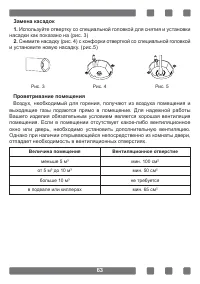
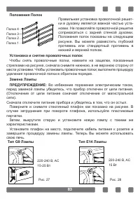
Page 63 - Проветривание помещения; Воздух, необходимый для горения, получают из воздуха помещения и; Величина помещения; не требуется
63 Замена касадок1. Используйте отвертку со специальной головкой для снятия и установки насадки как показано на (рис. 3) 2. Снимите насадку (рис. 4) с конфорки отверткой со специальной головкой и установите новую насадку. (pис.5) Проветривание помещения Воздух, необходимый для горения, получают из в...
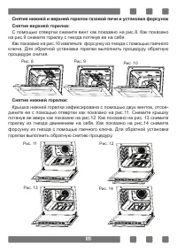
Page 65 - Снятие нижней горелки:
65 Снятие нижней и верхней горелок газовой печи и установка форсунок Снятие верхней горелки: С помощью отвертки снимите винт как показано на рис.8. Как показано на рис.9 снимите горелку с гнезда потянув ее на себя. Как показано на рис.10 извлечьте форсунку из гнезда с помощью гаечного ключа. Для обр...
Page 66 - ОПИСАНИЕ ИЗДЕЛИЯ
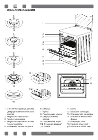
66 1. Стеклянная дверца духовки (Дверца из металлического листа) 2. Регулятор термостата 3. Регулятор духовки 4. Регулятор варочного отсека Переключатели 5. Нажимная кнопка поджига * 6. Дверца 7. Ручка 8. Пластиковая ножка 9. Дверца нижнего отсека 9.1 Выдвижной ящик * 9.2 Откидная дверца * 10. Лампа...
Page 67 - Принадлежности
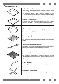
67 Принадлежности Держатель кофейника * Можно использовать, чтобы держать кофейник. Глубокий поднос * Используется для выпечки хлебо-булочных изделий, приго- товления больших запеканок, жидких блюд. Используется для выпекания кексов, а также в качестве сборника для жира в случае запекания мясных про...
Page 68 - Технические Характеристики Духового Шкафа; ПРЕДУПРЕЖДЕНИЕ
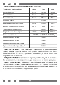
68 Технические Характеристики Духового Шкафа Технические характеристики 50x55 50x60 60x60 Внешняя ширина 500 мм 500 мм 600 мм Внешняя толщина 565 мм 630 мм 630 мм Внешняя высота 855 мм 855 мм 855 мм Мощность лампы 15-25 Вт Нижний нагревательный элемент 1000 Вт 1000 Вт 1200 Вт Верхний нагревательный ...
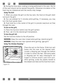
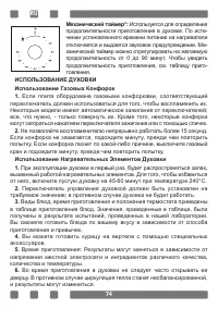
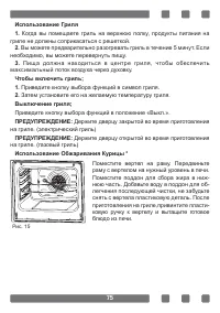
Page 75 - Использование Обжаривания Курицы *
75 Использование Гриля1. Когда вы помещаете гриль на верхнюю полку, продукты питания на гриле не должны соприкасаться с решеткой. 2. Вы можете предварительно разогревать гриль в течение 5 минут. Если необходимо, вы можете перевернуть пищу. 3. Пища должна находиться в центре гриля, чтобы обеспечить м...
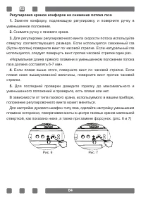
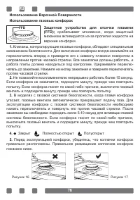
Page 76 - Защитное устройство для отсечки пламени
76 Использование Варочной ПоверхностиИспользование газовых конфорок Защитное устройство для отсечки пламени (FFD); срабатывает мгновенно, когда защитный механизм активируется из-за пролития жидкости на верхние конфорки. 1. Клапаны, контролирующие газовые конфорки, обладают специальным механизмом без...
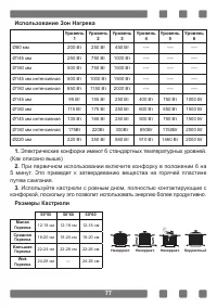
Page 77 - Использование Зон Нагрева; При первичном использовании включите конфорку в положении 6 на; Размеры Кастрюли
77 Использование Зон Нагрева Уровень 1 Уровень 2 Уровень 3 Уровень 4 Уровень 5 Уровень 6 Ø80 мм 200 Вт 250 Вт 450 Вт ---- ---- ---- Ø145 мм 250 Вт 750 Вт 1000 Вт ---- ---- ---- Ø180 мм 500 Вт 750 Вт 1500 Вт ---- ---- ---- Ø145 мм интенсивная 500 Вт 1000 Вт 1500 Вт ---- ---- ---- Ø180 мм интенсивная ...
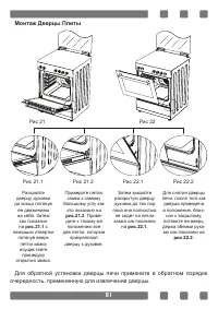
Page 81 - Монтаж Дверцы Плиты; Для обратной установки дверцы печи примените в обратном порядке
81 Монтаж Дверцы Плиты Для обратной установки дверцы печи примените в обратном порядке очередность, примененную для извлечения дверцы. Раскройте дверцу духовки до конца потянув ее движением на себя. Затем как показано на рис.21.1 с помощью отвертки потянув вверх петли замка осуществите процедуру отк...
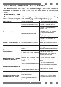
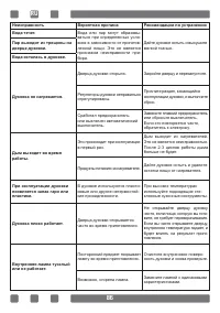
Page 85 - ниже и попробуйте устранить неполадку, выполнив рекомендации.
85 НАХОЖДЕНИЕ И УСТРАНЕНИЕ НЕИСПРАВНОСТЕЙ Вы можете решить проблемы, с которыми вы можете столкнуться в приборе, проверив следующие пункты перед тем, как обратиться в техническую службу. Контрольные точки Если у вас возникла проблема с духовкой, сначала проверьте таблицу ниже и попробуйте устранить ...
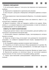
Page 87 - СОВЕТЫ ПО ЭНЕРГОСБЕРЕЖЕНИЮ
87 ПРАВИЛА ОБРАЩЕНИЯ1. Не используйте дверцу и / или ручку при переносе или перемещении прибора. 2. Переносите и перевозите в оригинальной упаковке. 3. При погрузке / разгрузке и обращении соблюдайте крайнюю осторож- ность. 4. Перед переносом и транспортировкой убедитесь, что упаковка надежно закрыт...