Page 2 - Table of Contents
Table of Contents General Power Tool Safety Warnings ...................................................................................... 4 Work Area Safety ................................................................................................................... 4 Electrical Safety ........
Page 4 - General Power Tool Safety Warnings; WARNING; vided with this power tool.; ElECTRICAl SAFETY; PERSONAl SAFETY
General Power Tool Safety Warnings WARNING Read all safety warnings, instructions, illustrations and specifications pro- vided with this power tool. Failure to follow all instructions listed below may result in electric shock, fire and/or serious injury. Save all warnings and instructions for future...
Page 6 - Functional Description
Functional Description Extension Pole Handle Stand-Up Extension Pole Strip Guide T rack Detachable Feed System Locking Clamp Slide Body Loading Point Tool-less Nose Piece Adjustment Pin Nose Piece Retention Screw Depth of Drive Indicator Depth of Drive Lock Button Depth of Drive Adjustment Knob
Page 7 - Tool Operation; Read sections titled “Safety Warnings” before operating tool.; INSTAllING A DS530-S1 OR DS530-M1 ADAPTER AND ATTACHMENT; locked; TOOl USE
Tool Operation Read sections titled “Safety Warnings” before operating tool. WARNING Do not use this product if it is not completely assembled or if any parts appear to be missing or damaged. Use of a product that is not properly and completely assembled or with damaged or missing parts could result...
Page 8 - ADJUSTING FASTENER lENGTH; Nosepiece has these possible settings:
TOOl USE 8 INSTAllING THE DS530-D1 OR DS530-D2 ADAPTER AND ATTACHMENT 1. To prepare the screw gun before installing the screw-on adapter. Adapter DeWalt Tool Output Shaft Assembly a. Unplug tool from electrical supply or remove battery before installing attachment.b. Remove the nose cone.c. Remove m...
Page 9 - CAUTION; ADJUSTING DEPTH OF DRIVE; DRIVING SCREWS
TOOl USE lOADING THE TOOl CAUTION beware of sharp points on screws. Avoid grabbing this area during loading and operation. 1 1. Make sure the heads of the screws are resting on top of the plastic colla- tion material. This will ensure proper strip advancement and prevent jamming. 2. Check for proper...
Page 10 - NOSEPIECE REPlACEMENT
TOOl USE 10 REVERSE OPERATIONTo operate tool in reverse for removal of screws (refer to Figure 1): 1. Flip the forward/reverse switch on the tool to reverse rotation. 2. Rotate the clamp on the attachment to the unlock position.3. Slide the attachment off the tool to expose the bit.4. Insert bit int...
Page 12 - Maintenance; Accessories; SPECIFICATION
12 Maintenance Read section titled “Safety Warnings” before maintaining tool. 1. With battery removed or cord disconnected, make daily inspection to ensure free movement of nosepiece and trigger. Do not use tool if nosepiece or trigger sticks or binds. 2. lubrication of the feed system is not necess...
Page 13 - Troubleshooting
13 Troubleshooting Problem/Symptom Probable Cause Corrective Action Tool will not fully drive fastener Bit is worn Replace bit Power capabilities of the tool have been exceeded Discontinue use in that application Tool is in reverse Switch tool to forward Incorrect bit installed Ensure correct bit ty...
Page 17 - Instrucciones de operación
KYOCERA-SENCO Industrial Tools, Inc. 8450 Broadwell Road Cincinnati, OH 45244 1-800-543-4596 www.senco.com © 2021 por KYOCERA-SENCO Industrial Tools, Inc. NFD810X • Emitido el 13 de junio de 2021 Serie DS530 ADITAMENTO DEL SISTEMA DE ALIMENTACIÓN AUTOMÁTICA DE TORNILLOS Instrucciones de operación IM...
Page 18 - Índice
Índice Advertencias generales de seguridad al usar herramientas eléctricas .................................................. 4 Seguridad en el área de trabajo .............................................................................................................. 4 Seguridad con la electricid...
Page 20 - SEGURIDAD EN EL ÁREA DE TRAbAjO; SEGURIDAD CON LA ELECTRICIDAD; SEGURIDAD PERSONAL
Advertencias generales de seguridad al usar herramientas eléctricas Lea todas las advertencias de seguridad, instrucciones, ilustraciones y especificaciones que se le proporcionan con esta herramienta eléctrica. El incumplimiento de todas las instrucciones enumeradas a continuación puede provocar de...
Page 21 - USO y CUIDADO DE LAS hERRAMIENTAS ELéCTRICAS; SERVICIO
14. Prevenir la puesta en marcha involuntaria. Asegúrese de que el interruptor esté en la posición de apagado antes de conectarlo a la fuente de alimentación o al paquete de la batería, levantar o transportar la herramienta. Llevar herramientas eléctricas con el dedo en el interruptor o energizar he...
Page 22 - Descripción funcional
Descripción funcional Mango del poste de extensión Poste de extensión con base Riel de la guía de las tiras Abrazadera de bloqueo del sistema de alimentación que se puede retirar Punto de carga del cuerpo deslizable Pasador de ajuste de la punta sin herramientas Tornillo de retención de la punta Ind...
Page 23 - Operación de la herramienta; INSTALACIÓN DEL ADITAMENTO y EL ADAPTADOR DS530-S1 O DS530-M1; bloqueado
Operación de la herramienta Lea las secciones tituladas “Advertencias de seguridad” antes de utilizar la herramienta. No use este producto si no está completamente ensamblado o si parece que faltan piezas o que están dañadas. El uso de un producto que no esté ensamblado de manera adecuada y completa...
Page 24 - INSTALACIÓN DEL ADITAMENTO y EL ADAPTADOR DS530-D1 O DS530-D2; AjUSTAR LA LONGITUD DEL SUjETADOR
USO DE LA hERRAMIENTA 8 INSTALACIÓN DEL ADITAMENTO y EL ADAPTADOR DS530-D1 O DS530-D2 1. Para preparar la pistola de tornillos antes de instalar el aditamento para atornillar. Adaptador Herramienta DeWalt Conjunto del eje de salida a. Desconecte la herramienta del suministro eléctrico o retire la ba...
Page 25 - CARGA DE LA hERRAMIENTA; AjUSTAR LA PROfUNDIDAD DE INSERCIÓN
USO DE LA hERRAMIENTA CARGA DE LA hERRAMIENTA Tenga cuidado con las puntas afiladas de los tornillos. Evite agarrar esta área durante la carga y la operación. 1 1. Asegúrese de que las cabezas de los tornillos descansen sobre el mate- rial plástico de unión. Esto asegurará que avancen adecuadamente ...
Page 26 - INSERCIÓN DE LOS TORNILLOS; OPERACIÓN INVERSA
USO DE LA hERRAMIENTA 10 INSERCIÓN DE LOS TORNILLOS 1. Siempre que sea posible, sostenga la herramienta en ángulo recto (perpendicular) a la superficie de trabajo. 2. Apriete el gatillo para arrancar el motor.3. Presione la punta con fuerza constante contra la superficie de trabajo. No retire la her...
Page 27 - REMPLAZO DE LA PUNTA
USO DE LA hERRAMIENTA 11 REMPLAZO DE LA PUNTA 1. Retire la batería o desenchufe la herramienta antes de cambiar la punta. 2. Retire el tornillo de retención. 3. Coloque la punta en el ajuste más largo posible.4. Presione el pasador selector de tornillo hasta que quede totalmente presionado. Será nec...
Page 28 - Especificaciones técnicas; ESPECIFICACIÓN
12 Mantenimiento Lea la sección titulada “Advertencias de seguridad” antes de dar mantenimiento a la herramienta. 1. Con la batería retirada o el cable desconectado, realice una inspección diaria para garantizar que la punta y el disparador se muevan libremente. No use la herramienta si la punta o e...
Page 29 - Resolución de problemas
13 Resolución de problemas Problema o síntoma Causa probable Acción correctiva La herramienta no inserta completamente el sujetador La broca está desgastada Reemplace la broca Se han excedido las capacidades de potencia de la herramienta Suspenda su uso en esa aplicación La herramienta está en rever...
Page 33 - Guide d’utilisation
KYOCERA-SENCO Industrial Tools, Inc. 8450 Broadwell Road Cincinnati, OH 45244 1 800 543-4596 www.senco.com © KYOCERA-SENCO Industrial Tools, Inc., 2021. NFD810X • Publié le 13 juin 2021 Série DS530 ACCESSOIRE POUR SYSTÈME DE VISSAGE À ALIMENTATION AUTOMATIQUE Guide d’utilisation IMPORTANT : À lire a...
Page 34 - Table des matières
Table des matières Avertissements de sécurité généraux concernant les outils électriques ............................... 4 Sécurité dans l’espace de travail............................................................................................ 4 Sécurité en électricité ............................
Page 36 - SÉCURITÉ DANS L’ESPACE DE TRAVAIL; SÉCURITÉ EN ÉLECTRICITÉ; SÉCURITÉ PERSONNELLE
Avertissements de sécurité généraux concernant les outils électriques Prenez connaissance de l’ensemble des avertissements de sécurité, instructions, illustrations et spécifications fournis avec cet outil électrique. Le non-respect des instructions indiquées ci-dessous peut entraîner une décharge él...
Page 37 - UTILISATION ET ENTRETIEN DES OUTILS ÉLECTRIQUES; RÉPARATION
13. Utilisez un équipement de protection individuelle. Portez toujours des lunettes de protection. L’utilisation d’un équipement de protection comme un masque antipoussière, des chaussures de sécurité antidérapantes, un casque de sécurité ou des protecteurs auriculaires dans des conditions approprié...
Page 38 - Description fonctionnelle
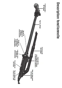
Description fonctionnelle Poignée de tige de rallonge Tige de rallonge Rail du guide de la bande Serre-joint de verrouillage du système d’alimentation amovible Point de chargement de la glissière Tige de réglage de la buse sans outil Vis de retenue de la buse Indicateur de la profondeur d’enfoncemen...
Page 39 - Utilisation de l’outil; UTILISATION DE L’OUTIL
Utilisation de l’outil Lisez les sections intitulées « Avertissements de sécurité » avant d’utiliser l’outil. N’utilisez pas ce produit s’il n’est pas complètement assemblé ou s’il semble y avoir des pièces manquantes ou endommagées. L’utilisation d’un produit mal assemblé ou pas complètement assemb...
Page 40 - RÉGLAGE DE LA LONGUEUR DE LA FIXATION; La buse comprend les réglages suivants :
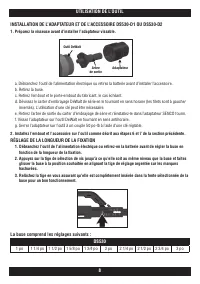
UTILISATION DE L’OUTIL 8 INSTALLATION DE L’ADAPTATEUR ET DE L’ACCESSOIRE DS530-D1 OU DS530-D2 1. Préparez la visseuse avant d’installer l’adaptateur vissable. Adaptateur Outil DeWalt Arbre de sortie a. Débranchez l’outil de l’alimentation électrique ou retirez la batterie avant d’installer l’accesso...
Page 41 - RÉGLAGE DE LA PROFONDEUR D’ENFONCEMENT
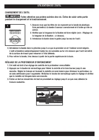
UTILISATION DE L’OUTIL ChARGEMENT DE L’OUTIL Faites attention aux pointes acérées des vis. Évitez de saisir cette partie pendant le chargement et le fonctionnement. 1 1. Assurez-vous que les têtes de vis reposent sur la bande de plastique. Cela permettra à la bande d’avancer correctement et d’éviter...
Page 42 - REMPLACEMENT DE L’EMbOUT
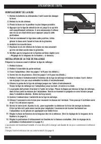
UTILISATION DE L’OUTIL 10 SERRAGE DES VIS 1. Dans la mesure du possible, maintenez l’outil dans un angle droit (perpendiculaire) par rapport à la surface de travail. 2. Appuyez sur la gâchette pour démarrer le moteur.3. Appuyez la buse avec une force constante contre la surface de travail. Ne retire...
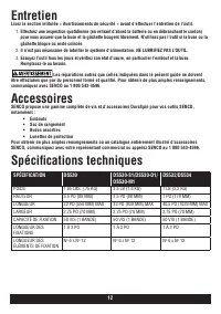
Page 44 - Entretien; Accessoires; Spécifications techniques; SPÉCIFICATION
12 Entretien Lisez la section intitulée « Avertissements de sécurité » avant d’effectuer l’entretien de l’outil. 1. Effectuez une inspection quotidienne (en retirant d’abord la batterie ou en débranchant le cordon) pour vous assurer que la buse et la gâchette bougent librement. N’utilisez pas l’outi...
Page 45 - Dépannage
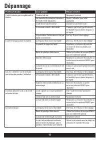
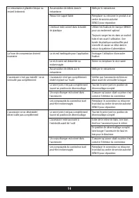
13 Dépannage Problème/Indicateur Cause probable Mesure corrective L’outil n’enfonce pas complètement la fixation L’embout est usé Remplacer l’embout Les capacités de puissance nécessaire de l’outil ont été dépassées Cesser l'utilisation pour cette application L’outil est en marche inverse Inverser l...
Page 49 - Screw Fastening System; SENCO TOOL & PARTS WARRANTY; Replacement of Tool Due to Natural Disaster
Screw Fastening System Questions? Comments? call SENCO’s toll-free Action-line: 1-800-543-4596 or e-mail: [email protected] Visit our Website www.senco.com Warnings for the safe use of this tool are included in this manual. Los avisos para el uso seguro de esta herramienta están incluidos en este ma...
Page 50 - ccica
2 l WARNING Read all safety warnings and all instructions. Failure to follow the warnings and instructions may result in electric shock, fire and/or serious injury. Save all warnings and instruc-tions for future reference. The term “power tool” in the warnings refers to your mains-operated (corded) ...
Page 54 - English Specifications
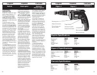
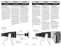
English Espanol Francais Switch FUNCTIONAL DESCRIPTION To start tool, depress the trigger switch, shown in Figure 1. To stop tool, release the switch. The variable speed trigger switch permits speed control. The farther the trigger switch is depressed, the higher the speed of the tool. To lock the s...
Page 55 - OPERATION
REPLACING THE BIT HOLDER AND BIT (FIGURE 2) Pull the locking sleeve. The locking sleeve and adjusting sleeve come out of the gear cas - ing as a set. Pull the bit holder straight out. If it is difficult to pull by hand, use pliers. Push a new bit into the holder. Use a new bit holder if necessary. P...