Page 2 - General information; C. DETERMING TOP LINE OF REAR WALL TEMPLATE; Installation Instructions
General information Introduction ...................................................................... 3 BEFORE YOU BEGIN .......................................................... 3 IMPORTANT SAFETY INSTALLATIONS ............................ 3 ELECTRICAL REQQUIREMENTS ................................
Page 3 - Introduction; Caution; ELECTRICAL REQUIREMENTS
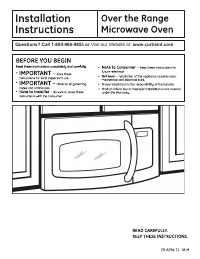
Note For easier installation and personal safety, it is recommended that two people install this product . Introduction This installation guide will show you how to install your new over-the-range microwave. BEFORE YOU BEGIN Read these instructions completely and carefully. • IMPORTANT – Save these ...
Page 4 - HOOD EXHAUST
DUCT PIECES EQUIVALENT LENGTH x NUMBER USED = EQUIVALENT LENGTH Roof Cap 24 Ft . x (1) = 24 Ft . 12 Ft . Straight Duct (6” Round) 12 Ft . x (1) = 12 Ft . Rectangular-to-Round Transition Adaptor* 5 Ft . x (1) = 5 Ft . Equivalen lengths of duct pieces are based on actual tests and reflect requirement ...
Page 5 - Maximum duct length:; not exceed 140 equivalent feet .; round duct should not exceed 140 equivalent feet .
Exhaust connection: The hood exhaust has been designed to made with a standard 3 1/4”x10” rectangular duct . If a round duct is required, a rectangular-to-round transiting adaptor must be used. Do not use less than a 6”diameter duct . Maximum duct length: For satisfactory air movement , the total du...
Page 6 - HARDWARE PACKET; PARTS INCLUDED; ADDITIONAL PARTS
HARDWARE PACKET DAMAGE-SHIPMENT/INSTALLATION • If the unit is damaged in shipment , return the unit to the store in which it was bought for repair or replacement . • If the unit is damaged by the customer, repair or replacement is the responsibility of the customer. • If the unit is damaged by the i...
Page 8 - PLACEMENT OF THE MOUNTING PLATE; A. REMOVING THE MICROWAVE OVEN FROM THE CARTON/REMOVING; Open the carton and remove the upper foam from the box, but; the upper foam; FINGING THE WALL STUDS; OR; Draw a line down the center of the wall studs.; THE MICROWAVE MUST BE CONNECTED TO AT LEAST ONE WALL STUD.
1. PLACEMENT OF THE MOUNTING PLATE A. REMOVING THE MICROWAVE OVEN FROM THE CARTON/REMOVING THE MOUNTING PLATE 1. Open the carton and remove the upper foam from the box, but remember to keep the accessories. 2. Pull the oven out of the carton and remove the plastic bag carefully. 3. Take the mounting...
Page 9 - TOP LINE OF REAR WALL TEMPLATE; Rear; DETERMING TOP LINE OF REAR WALL TEMPLATE LOCATION UNDER; The bottom of the cabinet have three types; Beneath flat bottom cabinet; TOP LINE OF REAR WALL TEMPLATE
TOP LINE OF REAR WALL TEMPLATE TOP LINE OF REAR WALL TEMPLATE Rear REAR WALL TEMPLATE Front REAR WALL TEMPLATE At least 30” C. DETERMING TOP LINE OF REAR WALL TEMPLATE LOCATION UNDER YOUR CABINET The bottom of the cabinet have three types 1. Beneath flat bottom cabinet TOP LINE OF REAR WALL TEMPLATE...
Page 10 - Beneath framed recessed cabinet; Must align with the back frame of cabinet bottom
Back frame of cabinet bottom TOP LINE OF REAR WALL TEMPLATE TOP LINE OF REAR WALL TEMPLATE REAR WALL TEMPLATE REAR WALL TEMPLATE Rear Front 2. Beneath framed recessed cabinet TOP LINE OF REAR WALL TEMPLATE Must align with the back frame of cabinet bottom 10 Installation Instructions
Page 11 - Beneath framed recesse bottom cabinet with front overhang; below cabinet bottom the same
3 . Beneath framed recesse bottom cabinet with front overhang TOP LINE OF REAR WALL TEMPLATE Must align with below cabinet bottom the same distance as the front overhang of cabinet bottom. Your cabinets may have decorative trim that interferes with the microwave installation. Remove the decorative t...
Page 12 - D. ALIGNING TOP LINE OF REAR WALL TEMPLATE; CAUTION: Wear gloves to avoid cutting fingers on sharp edges.; Center line
NOTE: DO NOT MOUNT THE PLATE AT THIS TIME. D. ALIGNING TOP LINE OF REAR WALL TEMPLATE CAUTION: Wear gloves to avoid cutting fingers on sharp edges. 1. Using tape measure, drawing a vertical line on the wall at the center of the 30” wide space. 2. Tape the rear wall template on the cabinet wall, alig...
Page 13 - A Charcoal Filter
See page 14 See page 22 See page 18 2. INSTALLATION TYPES (Choose A, B or C) This microwave oven is designed for adaptation to the following three types of ventilation: A: Outside Top Exhaust(Vertical Duct) B: Outside Back Exhaust(Horizontal Duct) C: Recirculating(Non-Vented Ductless) NOTE: This mic...
Page 14 - OUTSIDE TOP EXHAUST (Vertical Duct) DEFAULT; INSTALLATION OVERVIEW; and attach the toggle wings to 3⁄4” onto each machine screw (; To use toggle bolts
A. OUTSIDE TOP EXHAUST (Vertical Duct) DEFAULT INSTALLATION OVERVIEW A1 . ATTACH THE MOUNTING PLATE TO THE WALL A2 . USE TOP CABINET TEMPLATE FOR PREPARATION OF TOP CABINET A3. CHECK FOR PROPER DAMPER OPERATION A4. MOUNT THE MICROWAVE OVEN A5 . ADJUST THE EXHAUST ADAPTOR A6. CONNECTING DUCTWORK A1. ...
Page 15 - USE TOP CABINET TEMPLATE FOR PREPARATION OF TOP CABINET; You need to drill holes for; , a hole large enough for the power cord to fit through,; for recirculation exhaust .; CHECK FOR PROPER DAMPER OPERATION; microwave is installed.
A2. USE TOP CABINET TEMPLATE FOR PREPARATION OF TOP CABINET You need to drill holes for the top support screws , a hole large enough for the power cord to fit through, and a cutout large enough for the exhaust adaptor. • Place the microwave in its upright position, with the top of the unit facing up...
Page 16 - MOUNT THE MICROWAVE OVEN; microwave oven in place against the wall and the top cabinet .)
FOR EASIER INSTALLATION AND PERSONAL SAFETY, WE RECOMMEND THAT TWO PEOPLE INSTALL THIS MICROWAVE OVEN. IMPORTANT: D o not grip or use handle during installation. If filler blocks are not used, case damage may occur from over tightening screws. NOTE: If your cabinet is metal, use the nylon grommet ar...
Page 17 - Install grease filters. See the USER GUIDE packed with; ADJUST THE EXHAUST ADAPTOR; Extend the house duct down to connect to the exhaust adaptor.
6. Install grease filters. See the USER GUIDE packed with the microwave. A5. ADJUST THE EXHAUST ADAPTOR Open the top cabinet and adjust the exhaust adaptor to connect to the house duct . A6. CONNECTING DUCTWORK 1. Extend the house duct down to connect to the exhaust adaptor. 2. Seal exhaust duct joi...
Page 18 - PREPARING THE REAR WALL TEMPLATE FOR OUTSIDE BACK EXHAUST
B. OUTSIDE BACK EXHAUST (Horizontal Duct) INSTALLATION OVERVIEW B1. PREPARING THE REAR WALL TEMPLATE FOR OUTSIDE BACK EXHAUST. B2. ATTACH THE MOUNTING PLATE TO THE WALL. B3. USE TOP CABINET TEMPLATE FOR PREPARATION OF TOP CABINET. B4. ADAPTING MICROWAVE BLOWER FOR OUTSIDE BACK EXHAUST. B5. MOUNT THE...
Page 19 - ATTACH MOUNTING PLATE TO THE WALL; and a hole large enough for the power cord to fit through.; ADAPTING MICROWAVE BLOWER FOR OUTSIDE BACK EXHAUST
B2. ATTACH MOUNTING PLATE TO THE WALL Attach the mounting plate to the wall using the wing nuts and machine screws ( 3 ⁄ 16 ” x 3”). At least one wood screw must be used to attach the mounting plate to a wall stud. 1. Insert the machine screws ( 3 ⁄ 16 ” X 3”) into the mounting plate through the hol...
Page 21 - Tighten the outer two screws to the top of the microwave; o not grip or use handle during installation.
FOR EASIER INSTALLATION AND PERSONAL SAFETY, WE RECOMMEND THAT TWO PEOPLE INSTALL THIS MICROWAVE OVEN. 1. Lift microwave, tilt it forward, and hook slots at back bottom edge onto four lower tabs of mounting plate. 2. Rotate front of oven up against cabinet bottom. 3. Attach the microwave oven to the...
Page 23 - • Drill the holes, following the instructions on the TOP; CAUTION : Wear safety goggles when drilling holes in; ADAPTING BLOWER FOR RECIRCULATION; Replace the blower plate in the same position.
After C2. USE TOP CABINET TEMPLATE FOR PREPARATION OF TOP CABINET You need to drill holes for the top support screws and a hole large enough for the power cord to fit through. • Read the instructions on the TOP CABINET TEMPLATE. • Tape it underneath the top cabinet bottom. • Drill the holes, followi...
Page 25 - BEFORE YOU USE YOUR MICROWAVE; INSTALLATION
BEFORE YOU USE YOUR MICROWAVE 1. Make sure the microwave oven has been installed according to instructions. 6. Read the USER GUIDE. 2. Remove all packing material from the microwave oven. 7. KEEP INSTALLATION INSTRUCTIONS FOR THE LOCAL INSPECTOR’S USE. 3. Install turntable and ring in cavity. 4. Rep...
Page 26 - Visit our Website at:
Questions? Call 1-800-968-9853 or Visit our Website at: www.curtisint.com
Page 27 - C. DÉTERMINER L'EMPLACEMENT DE LA LIGNE; Instructions d’installation
Renseignements généraux Introduction ...................................................................... 3 AVANT DE COMMENCER .................................................. 3 CONSIGNES DE SÉCURITÉ IMPORTANTES ..................... 3 EXIGENCES ÉLECTRIQUES .........................................
Page 28 - Attention; EXIGENCES ÉLECTRIQUES
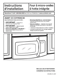
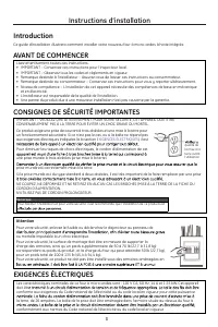
Remarque Pour faciliter l’installation et pour votre sécurité, il est recommandé que l’installation de ce produit soit Introduction Ce guide d’installation illustrera comment installer votre nouveau four à micro-ondes à hotte intégrée. AVANT DE COMMENCER Lisez attentivement toutes ces instructions. ...
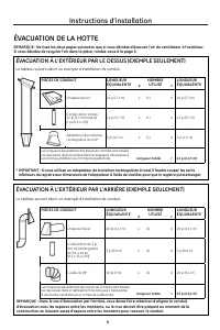
Page 29 - ÉVACUATION DE LA HOTTE; ÉVACUATION À L’EXTÉRIEUR PAR LE DESSUS (EXEMPLE SEULEMENT); Le tableau suivant décrit un exemple d’installation de conduit .
PIÈCES DE CONDUIT LONGUEUR ÉQUIVALENTE x NOMBRE UTILISÉ = LONGUEUR ÉQUIVALENTE Chapeau de toit 24 pi (7,3 m) x (1) = 24 pi (7,3 m) Conduit droit rond de 12 pi (3,7 m) (rond de 6 po [15,2 cm]) 12 pi (3,7 m) x (1) = 12 pi (3,7 m) Adaptateur de transition rectangulaire à rond* 5 pi (1,5 m) x (1) = 5 pi...
Page 30 - offrent
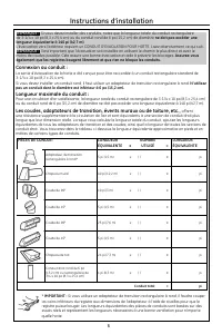
Connexion au conduit : La sortie d’évacuation de la hotte a été conçue pour être raccordée à un conduit rectangulaire standard de 3-1/4 x 10 po (8,3 x 25,4 cm). Si vous devez installer un conduit rond, il faut utiliser un adaptateur de transition rectangulaire à rond. N’utilisez pas un conduit dont ...
Page 31 - QUINCAILLERIE; DOMMAGES – EXPÉDITION/INSTALLATION; (s’il ne s’agit pas du client), la réparation ou le remplacement; PIÈCES COMPRISES; sachet fourni avec l’appareil. Vérifiez que vous avez; AUTRES PIÈCES
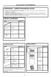
QUINCAILLERIE DOMMAGES – EXPÉDITION/INSTALLATION • Si l’appareil est endommagé durant le transport , retournez-le au magasin où vous l’avez acheté pour le faire réparer ou remplacer. • Si l’appareil est endommagé par le client , la réparation ou le remplacement reste à la charge du client . • Si l’a...
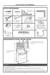
Page 32 - OUTILS NÉCESSAIRES
Tournevis Phillips nº 1 et nº 2 Crayon Équerre de menuisier (facultative) Cisailles de ferblantier (pour couper le registre, si nécessaire) Ciseaux (pour couper le gabarit , si nécessaire) Perceuse électrique avec forets de 3⁄16 po, 1⁄2 po et 5⁄8 po (4,8 mm, 13 mm et 15,9 mm) Entretoises d’assemblag...
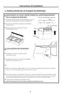
Page 33 - INSTALLATION DE LA PLAQUE DE MONTAGE; DE LA PLAQUE DE MONTAGE; Mousse d'emballage supérieure; LOCALISATION DES MONTANTS; A. Localisateur de montant – un dispositif magnétique; plus un son creux. Cela signifie que vous avez trouvé un montant .; LE FOUR À MICRO-ONDES DOIT ÊTRE FIXÉ À AU MOINS UN MONTANT DU MUR.
1. INSTALLATION DE LA PLAQUE DE MONTAGE A. ENLÈVEMENT DU FOUR À MICRO-ONDES DE LA BOÎTE/ENLÈVEMENT DE LA PLAQUE DE MONTAGE 1. Ouvrez la boîte et retirez la mousse d'emballage supérieure de la boîte. N'oubliez pas de conserver les accessoires. 2. Sortez le four de la boîte et retirez le sac en plasti...
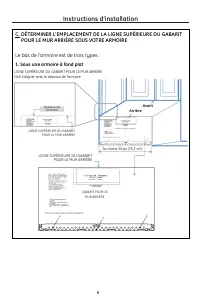
Page 34 - LIGNE SUPÉRIEURE DU GABARIT; Arrière; Avant; DÉTERMINER L'EMPLACEMENT DE LA LIGNE SUPÉRIEURE DU GABARIT; Sous une armoire à fond plat
LIGNE SUPÉRIEURE DU GABARIT POUR LE MUR ARRIÈRE LIGNE SUPÉRIEURE DU GABARIT POUR LE MUR ARRIÈRE Arrière GABARIT POUR LE MUR ARRIÈRE Avant GABARIT POUR LE MUR ARRIÈRE Au moins 30 po (76,2 cm) C. DÉTERMINER L'EMPLACEMENT DE LA LIGNE SUPÉRIEURE DU GABARIT POUR LE MUR ARRIÈRE SOUS VOTRE ARMOIRE Le bas d...
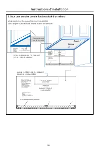
Page 35 - Sous une armoire dont le fond est doté d'un rebord; Doit s'aligner avec le cadre arrière du bas de l'armoire
Cadre arrière du bas de l'armoire LIGNE SUPÉRIEURE DU GABARIT POUR LE MUR ARRIÈRE LIGNE SUPÉRIEURE DU GABARIT POUR LE MUR ARRIÈRE GABARIT POUR LE MUR ARRIÈRE GABARIT POUR LE MUR ARRIÈRE Arrière Avant 2. Sous une armoire dont le fond est doté d'un rebord LIGNE SUPÉRIEURE DU GABARIT POUR LE MUR ARRIÈR...
Page 36 - Sous une armoire dotée d'un rebord avant; assurer qu’il est de niveau.; LE FOUR À MICRO-ONDES DOIT ÊTRE DE NIVEAU; de l’armoire, tel que décrit à l’étape D.; Dessous du bas de l'armoire à
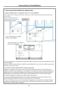
3 . Sous une armoire dotée d'un rebord avant LIGNE SUPÉRIEURE DU GABARIT POUR LE MUR ARRIÈRE Doit s'aligner avec le dessous du bas de l'armoire à la même distance que le bas du rebord avant de l'armoire Vos armoires peuvent être dotées de garnitures décoratives qui entravent l’installation du four à...
Page 37 - D. ALIGNER LA LIGNE SUPÉRIEURE DU GABARIT POUR LE MUR ARRIÈRE; Ligne centrale
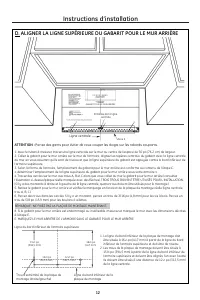
REMARQUE : NE FIXEZ PAS LA PLAQUE DE MONTAGE MAINTENANT. D. ALIGNER LA LIGNE SUPÉRIEURE DU GABARIT POUR LE MUR ARRIÈRE ATTENTION : Portez des gants pour éviter de vous couper les doigts sur les rebords coupants. 1. Avec le ruban à mesurer, tracez une ligne verticale sur le mur au centre de l’espace ...
Page 38 - Pour une évacuation sans conduit ,
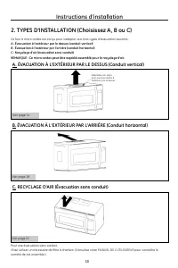
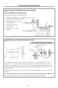
Voir page 14 Voir page 22 Voir page 18 2. TYPES D'INSTALLATION (Choisissez A, B ou C) Ce four à micro-ondes est conçu pour s’adapter aux trois types d’évacuation suivants : A : Évacuation à l’extérieur par le dessus (conduit vertical) B : Évacuation à l’extérieur par l’arrière (conduit horizontal) C...
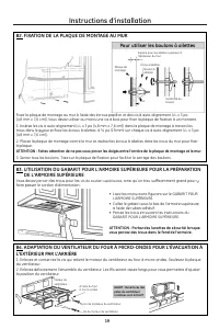
Page 39 - VUE D’ENSEMBLE DE L'INSTALLATION; FIXATION DE LA PLAQUE DE MONTAGE AU MUR; x 3 po; Pour utiliser les boulons à ailettes
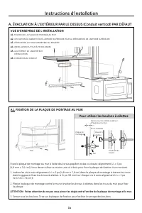
A. ÉVACUATION À L’EXTÉRIEUR PAR LE DESSUS (Conduit vertical) PAR DÉFAUT VUE D’ENSEMBLE DE L'INSTALLATION A1 . FIXATION DE LA PLAQUE DE MONTAGE AU MUR A2 . UTILISATION DU GABARIT POUR L'ARMOIRE SUPÉRIEURE POUR LA PRÉPARATION DE L'ARMOIRE SUPÉRIEURE A3. VÉRIFICATION DU FONCTIONNEMENT DU REGISTRE A4. I...
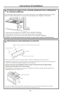
Page 40 - DE L'ARMOIRE SUPÉRIEURE; Vous devez percer des trous pour les; , un trou suffisamment grand pour y faire; l’arrière. Il est absent des modèles expédiés pour recyclage d’air.; librement avant d’installer le four à micro-ondes.; l’adaptateur avec la vis à tôle fournie.; VÉRIFICATION DU FONCTIONNEMENT DU REGISTRE
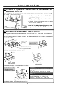
A2. UTILISATION DU GABARIT POUR L'ARMOIRE SUPÉRIEURE POUR LA PRÉPARATION DE L'ARMOIRE SUPÉRIEURE Vous devez percer des trous pour les vis de soutien supérieures , un trou suffisamment grand pour y faire passer le cordon d’alimentation et une ouverture assez grande pour l’adaptateur d’évacuation. • P...
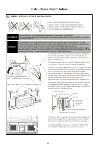
Page 41 - de resserrer les vis.; temporairement le four en vissant la vis d'au moins deux; INSTALLATION DU FOUR À MICRO-ONDES; Faites faire deux tours complets à chaque vis.
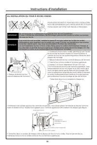
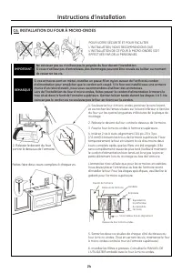
POUR VOTRE SÉCURITÉ ET POUR FACILITER L’INSTALLATION, NOUS RECOMMANDONS QUE L’INSTALLATION DE CE FOUR À MICRO-ONDES SOIT EFFECTUÉE PAR DEUX PERSONNES. IMPORTANT : Ne saisissez pas ou n’utilisez pas la poignée du four durant l’installation. Si vous n’utilisez pas d’entretoises, des dommages peuvent ê...
Page 42 - Installez les filtres à graisses. Consultez le MANUEL DE; AJUSTEMENT DE L’ADAPTATEUR D’ÉVACUATION
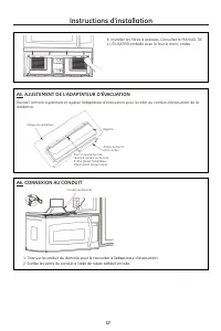
6. Installez les filtres à graisses. Consultez le MANUEL DE L'UTILISATEIR emballé avec le four à micro-ondes. A5. AJUSTEMENT DE L’ADAPTATEUR D’ÉVACUATION Ouvrez l’armoire supérieure et ajustez l’adaptateur d’évacuation pour le relier au conduit d’évacuation de la résidence. A6. CONNEXION AU CONDUIT ...
Page 43 - ÉVACUATION À L’EXTÉRIEUR PAR L’ARRIÈRE; B1. PRÉPARATION DU GABARIT POUR LE MUR ARRIÈRE POUR L’ÉVACUATION À; arrière pour l’évacuation à l’extérieur.
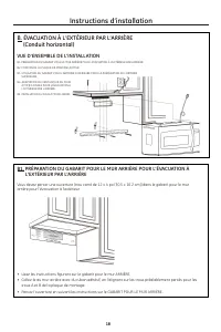
B. ÉVACUATION À L’EXTÉRIEUR PAR L’ARRIÈRE (Conduit horizontal) VUE D’ENSEMBLE DE L'INSTALLATION B1. PRÉPARATION DU GABARIT POUR LE MUR ARRIÈRE POUR L’ÉVACUATION À L’EXTÉRIEUR PAR L’ARRIÈRE B2. FIXATION DE LA PLAQUE DE MONTAGE AU MUR B3. UTILISATION DU GABARIT POUR L'ARMOIRE SUPÉRIEURE POUR LA PRÉPAR...
Page 44 - , ainsi qu’un trou suffisamment grand pour y; Lisez les instructions figurant sur le GABARIT POUR; ATTENTION : Portez des lunettes de sécurité lorsque; L’EXTÉRIEUR PAR L’ARRIÈRE; la position du ventilateur.
B2. FIXATION DE LA PLAQUE DE MONTAGE AU MUR Fixez la plaque de montage au mur à l'aide des écrous papillon et des vis à auto-alignement ( 3 ⁄ 16 x 3 po [4,8 mm x 7,6 cm]). Vous devez utiliser au moins une vis à bois pour fixer la plaque de fixation à un montant . 1. Insérez les vis à auto-alignement...
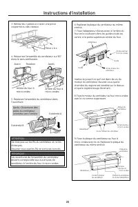
Page 48 - ADAPTATION DU VENTILATEUR POUR LE RECYCLAGE D'AIR; position du ventilateur.; Replacez la plaque du ventilateur au même endroit .; • Lisez les instructions figurant sur le GABARIT POUR; Ne tirez pas sur les fils du ventilateur et ne les
C3. ADAPTATION DU VENTILATEUR POUR LE RECYCLAGE D'AIR 1. Enlevez et conservez la vis qui retient le moteur du ventilateur au four à micro-ondes. Soulevez la plaque du ventilateur. 2. Enlevez délicatement l’ensemble du ventilateur. Les fils seront assez longs pour vous permettre d’ajuster la position...
Page 50 - AVANT D’UTILISER VOTRE FOUR À MICRO-ONDES; installé conformément aux directives.
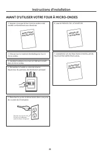
AVANT D’UTILISER VOTRE FOUR À MICRO-ONDES 1. Assurez-vous que le four à micro-ondes a été installé conformément aux directives. 6. Lisez le MANUEL DE L'UTILISATEUR. 2. Enlevez tout le matériel d’emballage du four à micro-ondes. 7. CONSERVEZ LES INSTRUCTIONS D’INSTALLATION POUR VOTRE INSPECTEUR LOCAL...