Page 2 - Warranty and Service
2 Warranty and Service Powermatic warrants every product it sells against manufacturers’ defects. If one of our tools needs service or repair, please contact Technical Service by calling 1-800-274-6846, 8AM to 5PM CST, Monday through Friday. Warranty Period The general warranty lasts for the time pe...
Page 3 - Table of Contents
3 Table of Contents Warranty and Service .................................................................................................................................... 2 Table of Contents ...........................................................................................................
Page 4 - Read, understand and follow
4 Warning As with all machines, there is a certain amount of hazard involved with the use of this planer. Use the machine with the respect and caution demanded where safety precautions are concerned. When normal safety precautions are overlooked or ignored, personal injury to the operator can result...
Page 5 - If you are not
5 Hand safety. Keep hands outside the machine. NEVER reach under the guards to try to clear stock that stops feeding. Do not clear chips and sawdust with hands; use a brush. Do not have any part of the hands under that part of the board that is over the table when starting a cut; the infeed roll wil...
Page 6 - Introduction; Features
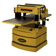
6 Introduction This manual is provided by Powermatic covering the safe operation and maintenance procedures for a Powermatic Model 209 and 209HH Planer. This manual contains instructions on installation, safety precautions, general operating procedures, maintenance instructions and parts breakdown. ...
Page 7 - Specifications
7 Specifications Model Number ....................................................................... 209-1 ....................................................... 209-3 Stock Number .................................................................. 1791296 .............................................
Page 8 - Unpacking
8 Unpacking Open shipping container and check for shipping damage. Report any damage immediately to your distributor and shipping agent. Do not discard any shipping material until the Planer is assembled and running properly. Compare the contents of your container with the following parts list to ma...
Page 9 - Assembly; Use care when cleaning; Handwheel
9 Assembly Tools required for assembly: Forklift or hoist with slings Pliers Open-End Wrenches 10,12,13,19mm Hex Wrenches, 4 and 5mm – provided Remove the screws holding the planer to the pallet and use a forklift or hoist to lift the planer off the pallet. Forks and straps should always be placed u...
Page 10 - do not; Electrical Connections; Electrical connections must
10 Extension Tables 1. Mount a cast iron table to the edge of the main table with three M8 x 25 hex cap screws (Figure 9) using a 13mm wrench. Do not fully tighten yet. 2. The extension table must be leveled with the main table. Place a straight edge (such as a jointed board) across both tables. 3. ...
Page 11 - Extension Cords; Adjustments; Tools required for adjustments:; Belt Tension; Table Rollers; Recommended Gauges (AWG) of Extension Cords
11 Extension Cords The use of an extension cord is not recommended for this machine, but if one proves necessary make sure the cord rating is suitable for the amperage listed on the machine's motor plate. An undersized cord will cause a drop in line voltage resulting in loss of power and overheating...
Page 12 - IMPORTANT; Cutterhead
12 When planing smooth stock the rollers should be set at low position. NOTE: When raising the roller higher above the table, the range is from .003" to .006" (Figure 14). The table rollers are factory set for average planing and are parallel to the table surface. If you desire to adjust the...
Page 13 - After setting or installing; Replacing and Re-setting Knives
13 4. If an adjustment to one or more of the knives is necessary, slightly loosen the knife gib (E, Figure 18) by turning the six screws (F, Figure 18) into the gib (i.e. clockwise, when facing the screw heads) with a 12mm hex wrench. Turn the screws just enough to relieve stress in the cutterhead w...
Page 14 - After replacing and checking; Replacing or Rotating Knife Inserts
14 6. Inspect the cutting edge of the knives for nicks or wire edge. Hone the knives slightly using a stone or if the knives are to be sharpened, maintain a cutting angle of 35 degrees. 7. Insert springs, knife and gib into slot of cutterhead. Back out screws just enough to hold the knife in the cut...
Page 15 - Make sure all knife insert; Work Table Parallel to Cutterhead
15 Make sure all knife insert screws are tightened securely. Loose inserts can be propelled at high speed from a rotating cutterhead, causing injury. Work Table Parallel to Cutterhead The work table is set parallel to the cutterhead at the factory and no further adjustment should be necessary. If yo...
Page 18 - Do not attempt to change; Changing Accessories for Lowest
18 Pressure Bar Height The pressure bar prevents the stock from lifting after it passes under the cutterhead. Check the height of the pressure bar with your gauge block and a .008" (0.2mm) feeler gauge. If adjustment is needed: 1. Remove top cover. 2. Loosen the lock nuts (B, Figure 29) on both ...
Page 20 - Maintenance; Disconnect machine from; Lubrication; GEARBOX LUBRICANT
20 Maintenance Disconnect machine from power source before performing any maintenance. Periodic or regular inspections are required to ensure that the machine is in proper adjustment, that all screws are tight, that belts are in good condition, that dust has not accumulated in the electrical enclosu...
Page 22 - Troubleshooting: Operating Problems; Trouble
22 Troubleshooting: Operating Problems Trouble Probable Cause Remedy Snipe. (NOTE: Snipe cannot be eliminated, but can be so minimized as to be negligible.) Table rollers not set properly. Adjust rollers to proper height. Inadequate support of long boards. Support long boards with extension rollers....
Page 23 - Troubleshooting: Mechanical and Electrical Problems
23 Troubleshooting: Mechanical and Electrical Problems Trouble Probable Cause Remedy Uneven depth of cut side to side. Knife projection from cutterhead is incorrect (209 only) Adjust knife projection. Table not parallel to cutterhead. Adjust table/cutterhead parallelism. Board thickness does not mat...
Page 24 - Optional Accessories; Replacement Parts
24 Trouble Probable Cause Remedy Machine will not start/restart or repeatedly trips circuit breaker or blows fuses. (cont.) Motor starter failure. Examine motor starter for burned or failed components. If damage is found, replace motor starter. If motor starter looks okay but is still suspect, you h...
Page 25 - Cutterhead Assembly
Page 26 - Parts List: Cutterhead Assembly; Description
26 Parts List: Cutterhead Assembly Index No. Part No. Description Size Qty 1 ................ 6012204 .................... Nut ........................................................................... 5/16-18NC .................... 2 2 ................ 6292622 .................... Knife Locking Ba...
Page 28 - Base Assembly
Page 29 - Parts List: Base Assembly
29 Parts List: Base Assembly Index No. Part No. Description Size Qty 1 ................ 6292649 .................... Ring, Retaining ........................................................ STW-12 ......................... 1 2 ................ 6292742 .................... Gear .........................
Page 31 - Parts List: Gearbox Assembly
31 Parts List: Gearbox Assembly Index No. Part No. Description Size Qty 1 ................ 6292788 .................... Socket Head Cap Screw ......................................... M6 x 1.0P x 25L ............ 5 2 ................ 6292785 .................... Pin ....................................
Page 35 - Electrical Connections – Single Phase, 230 Volt only
35 Electrical Connections – Single Phase, 230 Volt only
Page 36 - Electrical Connections – 3 Phase, 230 Volt only
36 Electrical Connections – 3 Phase, 230 Volt only 4T2 ManAuto 97 A2 95 R 96 O R 14NO 6T3 17 98 2T1 3L2 13NO 5L3 1L1 A1
Page 37 - Electrical Connections – 3 Phase, 460 Volt only
37 Electrical Connections – 3 Phase, 460 Volt only 4T2 ManAuto 97 A2 95 R 96 O R 14NO 6T3 17 98 2T1 3L2 13NO 5L3 1L1 A1
Page 38 - Preventive Maintenance; Checklist for Model 209 and 209HH Planers
38 Preventive Maintenance Checklist for Model 209 and 209HH Planers [ ] Work area around machine marked off clearly. [ ] Non-skid floor strips in area where operator normally stands. [ ] Inspect entire machine for loose bolts, nuts, screws. Tighten and replace as necessary. [ ] Clean table and cutte...