Page 2 - Warranty and Service
2 Warranty and Service Powermatic warrants every product it sells against manufacturers’ defects. If one of our tools needs service or repair, please contact Technical Service by calling 1-800-274-6846, 8AM to 5PM CST, Monday through Friday. Warranty Period The general warranty lasts for the time pe...
Page 3 - Table of Contents
3 Table of Contents Warranty and Service .............................................................................................................................. 2 Table of Contents .................................................................................................................
Page 8 - Installing Dust Hood; Grounding Instructions; Electrical connections must
8 Installing Dust Hood Mount the dust hood with the eight M6 x 10mm hex screws, eight spring washers, and eight flat washers. See Figure 3. It is strongly recommended that a dust collection system be connected to the 5” port on the planer’s dust hood. The system should be of sufficient volume for th...
Page 9 - Depth of Cut; Feed Rate Adjustment; Always change speeds while; Belt Tension
9 Inspection Before putting power to the machine, check that all screws are tight, that all mechanical functions work freely and that the cutterhead turns freely without knife contact with the chipbreaker or pressure bar. On the helical cutterhead model, check that all knife inserts are properly tor...
Page 10 - Opening Hood; Use care when placing hands
10 Opening Hood To open the hood for access to the cutterhead, remove the two hex screws with the 22mm wrench provided. See Figure 7. Knife Installation and Adjustment (Straight Cutterhead only) Use care when placing hands near knives as they are extremely sharp and can cause severe cuts. Installing...
Page 12 - The Planer’s Feed System; Anti-Kickback Fingers
12 The Planer’s Feed System (Refer to Figure 11) 1. Anti-kickback fingers 2. Infeed roller 3. Chipbreaker 4. Cutterhead 5. Pressure bar 6. Outfeed roller Anti-Kickback Fingers Anti-kickback fingers help prev ent stock from being thrown from the machine. These fingers operate by gravity and should be...
Page 13 - Chipbreaker; A chipbreaker set too low or; Pressure Bar
13 6. Mov e the gauge to the extreme right end of the infeed roller and check. Make similar adjustments if needed. 7. Tighten hex nuts (A, Figure 14) when finished. IMPORTANT: The setting on both ends of the infeed roller must be the same to avoid skewing of the material as it is fed through the mac...
Page 15 - Table Adjustments
15 5. If the gauge reading is greater or less than zero, reach beneath the table with a wrench and loosen the hex nut (C, Figure 17) which is abov e the cam (D, Figure 17) near the end of the roller that needs adjusting. Rotate the hex cap screw (E, Figure 17) until the gauge reads zero. 6. Repeat t...
Page 16 - Operating Controls; Never stand directly in line; Washboard Finish
16 Operating Controls The stop button is a mushroom style button which is conv enient for “emergency” shutdowns. After being pushed, the stop button remains engaged. To re-start the planer, twist the stop button clockwise until it pops back out. Test Cutting and Troubleshooting Using a piece of semi...
Page 17 - Disconnect machine from power
17 Snipe Some amount of snipe may be inevitable with many planer operations, but proper planer adjustments can so minimize snipe as to make it negligible. If noticeable snipes appear on each end of the material, as shown in Figure 22, a table roller is too high causing a slight lift of the material ...
Page 18 - Never attempt pressure bar; Halted Feeding; Maintenance; Use caution and proceed; Lubrication
18 Never attempt pressure bar adjustment while planer is connected to power. Feed restriction can also occur due to pitch buildup on the table. Be sure the table surface is clean. Occasionally dusting the surface with talc will aid in smoother feeding and help prevent pitch buildup. Halted Feeding I...
Page 19 - Planer Operating Problems; Trouble Probable
19 Troubleshooting: Planer Operating Problems Trouble Probable Cause Remedy Snipe. Table rollers not set properly. Adjust table rollers to proper height. Inadequate support of long boards. Support long boards with a roller stand. Unev en feed roller pressure front to back. Adjust feed roller tension...
Page 20 - Mechanical and Electrical Problems
20 Troubleshooting: Mechanical and Electrical Problems Trouble Probable Cause Remedy Unev en depth of cut side to side. Knives not set correctly. Make sure knives are set correctly and securely in cutterhead. Planer table not parallel to cutterhead. Adjust table parallel to cutterhead. See page 15. ...
Page 21 - Replacement Parts
21 Trouble Probable Cause Remedy Machine will not start/restart or repeatedly trips circuit breaker or blows fuses. (continued) Starter or motor failure (how to distinguish). Examine motor starter for burned or failed components. If damage is found, replace motor starter. If you hav e access to a v ...
Page 22 - Parts List: Base Assembly; Description
22 Parts List: Base Assembly Index No. Part No. Description Size Qty 1 ............... 6012068...................Rubber Boot .......................................................................................... 2 2 ............... 6012069...................Lead Screw ..............................
Page 24 - Gearbox Assembly
Page 25 - Parts List: Gearbox Assembly
25 Parts List: Gearbox Assembly Index No. Part No. Description Size Qty ................. 201-100 ...................Gearbox Assembly ................................................................................ 1 1 ............... 6012034...................Gearbox Body .............................
Page 26 - Column Assembly
Page 27 - Parts List: Column Assembly
27 Parts List: Column Assembly Index No. Part No. Description Size Qty 1 ............... 6012193...................Lifting Eye ..........................................................M20 x 2.5P x 30Lg ...... 2 2 ............... 6012194...................Left Column ...................................
Page 28 - Table Assembly
Page 29 - Parts List: Table Assembly
29 Parts List: Table Assembly Index No. Part No. Description Size Qty 1 ............... 6012233...................Bracket .................................................................................................. 4 2 ............... BB-6203ZZ ..............Ball Bearing .........................
Page 30 - Parts List: Top Cover Assembly
30 Parts List: Top Cover Assembly Index No. Part No. Description Size Qty 1 ............... 6012181...................Dust Hood ............................................................................................. 1 2 ............... 6012091...................Screw .............................
Page 31 - Cutterhead Assembly
Page 32 - Parts List: Cutterhead Assembly
32 Parts List: Cutterhead Assembly Index No. Part No. Description Size Qty 1 ............... 6012131...................Socket Head Cap Screw .....................................M10 x 1.5P x 75Lg ...... 2 2 ............... 6012080...................Flat W asher .........................................
Page 34 - Electrical Connections – 1 Phase, 230 Volt
Page 35 - Electrical Connections – 3 Phase, 230 Volt
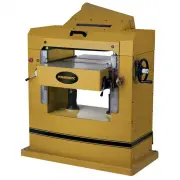