Page 2 - Warranty and Service
2 Warranty and Service Powermatic warrants every product it sells against manufacturers’ defects. If one of our tools needs service or repair, please contact Technical Service by calling 1-800-274-6846, 8AM to 5PM CST, Monday through Friday. Warranty Period The general warranty lasts for the time pe...
Page 3 - Table of Contents
3 Table of Contents Warranty and Service .................................................................................................................................... 2 Table of Contents ...........................................................................................................
Page 4 - Read, understand and follow; Electrical grounding.; Disconnect machine
4 Warning As with all machines, there is a certain amount of hazard involved with the use of this planer. Use the machine with the respect and caution demanded where safety precautions are concerned. When normal safety precautions are overlooked or ignored, personal injury to the operator can result...
Page 5 - Cutterhead rotation:; If you are not
5 Hand safety. Keep hands outside the machine. NEVER reach under the guards to try to clear stock that stops feeding. Do not clear chips and sawdust with hands; use a brush. Do not have any part of the hands under that part of the board that is over the table when starting a cut; the infeed roll wil...
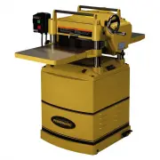
Page 6 - Features; Specifications
6 Features Figure 1 Specifications Model Number ....................................................................................... 15S .................................................. 15HH Stock Number ............................................................................... 1791210 ......
Page 7 - Unpacking; Crate Contents
7 Unpacking Open container and check for shipping damage. Report any damage immediately to your distributor and shipping agent. Do not discard any shipping material until the Planer is assembled and running properly. Compare the contents of your container with the following list to make sure all par...
Page 8 - Installation and Assembly; Use care when cleaning; Handwheel; Starter Box
8 Installation and Assembly Tools required for assembly: Forklift or hoist with slings 10,12,13,16mm open-end wrenches 4 and 5mm hex wrenches (provided) 16mm open-end wrench Remove the screws holding the planer to the pallet and use a forklift or hoist to lift the planer off the pallet. Forks and st...
Page 9 - Extension Tables; Dust Hood; Electrical connections must; Local codes take precedence over
9 Extension Tables 1. Mount a cast iron table to the edge of the main table with three M8 x 25 hex capscrews (Figure 9) using a 13mm wrench. Donot fully tighten yet. 2. The extension table must be leveled with the main table. Place a straight edge (such as ajointed board) across the extension tablea...
Page 10 - Extension Cords; Adjustments; Belt Tension
10 This machine must be grounded. Grounding provides a path of least resistance to help divert current away from the operator in case of electrical malfunction. Make sure the voltage of your power supply matches the specifications on the motor plate of the machine. Extension Cords The use of an exte...
Page 12 - Cutterhead; Use caution and proceed
12 IMPORTANT: Be sure that the height of front and rear rollers are the same. And the table rollers must always be set parallel to the table. Cutterhead Although your planer was carefully adjusted at the factory, it should be checked before being put into operation. Any inaccuracies due to rough han...
Page 13 - After installing knives, check; Make sure all knife insert
13 (You can also use any 3mm diameter tool, such as a hex wrench or drill bit for this purpose.) 9. Insert the screws for the first gib, turning them with the T-handle wrench. Do not fullytighten the screws; make them only snugenough to hold the knife in the groove. 10. Put the next gib in place, an...
Page 17 - Always re-install cover over; Stock Return Rollers
17 Chip Deflector The chip deflector (B, Fig. 28) keeps wood chips from falling into the outfeed roller. The deflector should be set approximately 1/16" to 1/8” from the tip of the knives. Make sure the deflector is oriented so the bevel on its front edge matches the shape of the cutterhead. Fee...
Page 18 - Depth of Cut; Maintenance; Disconnect machine from; Lubrication; Gearbox Lubricant
18 Depth of Cut The cutting depth scale is a combination inch/metric scale (Figure 33), with a cutting range from 0 to 6" (152.4mm). A manual scale is mounted directly to the front column. The model 15S planer also features a digital scale for easier, more precise depth readings. Figure 33 The d...
Page 21 - TOL; Scale Alignment; Method 1
21 From this point on, any table movement will be based off this setting. The setting will be kept in the device’s memory even when the digital display is turned off, and only needs re-setting after a battery has lost charge and needs replacing. TOL – tolerance setting This function is not generally...
Page 22 - Method 2; Using Relative Measurement Mode
22 Method 2 uses a scrap board and calipers. 1. Turn on the digital display. It turns on in absolute mode. 2. Plane one side of a scrap board at an appropriate and safe cutting depth (1/16” forexample). 3. Raise the table by the same amount (1/16”), then turn the board over and plane the otherside. ...
Page 23 - Troubleshooting: Performance Problems; Trouble
23 Troubleshooting: Performance Problems Trouble Probable Cause Remedy Snipe. (NOTE: Snipe cannot be eliminated, but can be so minimized as to be negligible.) Table rollers not set properly. Adjust rollers to proper height. Inadequate support of long boards. Support long boards with extension roller...
Page 24 - Troubleshooting: Mechanical and Electrical Problems
24 Troubleshooting: Mechanical and Electrical Problems Trouble Probable Cause Remedy Uneven depth of cut side to side. Knife projection from cutterhead is incorrect (15S only). Adjust knife projection. Table not parallel to cutterhead. Adjust table/cutterhead parallelism. Board thickness does not ma...
Page 26 - Troubleshooting: Digital Scale; Switch Lock; Optional Accessories; Replacement Parts
26 Troubleshooting: Digital Scale – Model 15S only Trouble Probable Cause Remedy Flashing digits. Low voltage. Replace battery. Locked digits. Haphazard memory. Take battery out, wait thirty seconds, then re-insert it. No display. Poor contact of battery. Improve battery contact. Low voltage. Replac...
Page 27 - Head Assembly
Page 28 - Parts List: Head Assembly; Description
28 Parts List: Head Assembly Index No. Part No. Description Size Qty ................. 15S-201 ................... Cutterhead Assembly (Items 3 thru 9) ................. .................................... 1 1 ............... 6284753 ................... Roller Case ....................................
Page 30 - Base Assembly
Page 31 - Parts List: Base Assembly
31 Parts List: Base Assembly Index No. Part No. Description Size Qty 1 ............... 6284703 ................... Base ..................................................................... .................................... 1 2 ............... TS-1525021 ............. Socket Set Screw ..............
Page 32 - Table Assembly
Page 33 - Parts List: Table Assembly
33 Parts List: Table Assembly Index No. Part No. Description Size Qty 1 ............... 15S-301 ................... Table .................................................................... .................................... 1 2 ............... 6284732 ................... Table Roller ..............
Page 34 - Gearbox Assembly
Page 35 - Parts List: Gearbox Assembly
35 Parts List: Gearbox Assembly Index No. Part No. Description Size Qty ................. 6284842 ................... Gearbox Assembly (Items 1 thru 35) ................... .................................... 1 1 ............... TS-1504101 ............. Socket Head Cap Screw ..........................
Page 36 - Cabinet Assembly
Page 37 - Parts List: Cabinet Assembly
37 Parts List: Cabinet Assembly Index No. Part No. Description Size Qty ................. 6284875 ................... Cabinet Assembly (Items 1 thru 29) .................... .................................... 1 1 ............... 15S-501 ................... Cabinet ....................................
Page 38 - Electrical Connections – Single Phase, 230 Volt
38 Electrical Connections – Single Phase, 230 Volt 95 R ManAuto 96 97 98 O R 14NO A2 17 4T2 6T3 2T1 13NO 5L3 3L2 A1 1L1
Page 39 - Preventive Maintenance; Checklist for Model 15S and 15HH Planers
39 Preventive Maintenance Checklist for Model 15S and 15HH Planers [ ] Work area around machine marked off clearly. [ ] Non-skid floor strips in area where operator normally stands. [ ] Inspect entire machine for loose bolts, nuts, screws. Tighten and replace as necessary. [ ] Clean table and cutter...