Page 2 - Warranty and Service
2 1.0 Warranty and Service Powermatic ® warrants every product it sells against manufacturers’ defects. If one of our tools needs service or repair, please contact Technical Service by calling 1-800-274-6846, 8AM to 5PM CST, Monday through Friday. Warranty Period The general warranty lasts for the t...
Page 3 - Table of contents
3 2.0 Table of contents Section Page 1.0 Warranty and Service ..................................................................................................................................... 2 2.0 Table of contents ...................................................................................
Page 4 - Safety warnings
3.0 Safety warnings 1. Read and understand the entire owner's manual before attempting assembly or operation. 2. Read and understand the warnings posted on the machine and in this manual. Failure to comply with all of these warnings may cause serious injury. 3. Replace the warning labels if they bec...
Page 5 - Kickback; Kickback Prevention
5 29. Never leave the machine running unattended. Turn the power off and do not leave the machine until it comes to a complete stop. 30. Remove loose items and unnecessary work pieces from the area before starting the machine. 31. Keep hands out of the line of saw blade. 32. Use a push-stick when re...
Page 6 - About this manual
6 Familiarize yourself with the following safety notices used in this manual: This means that if precautions are not heeded, it may result in minor injury and/or possible machine damage. This means that if precautions are not heeded, it may result in serious injury or possibly even death. 4.0 About ...
Page 7 - Glossary
7 5.0 Glossary Arbor: Metal shaft that connects the drive mechanism to the blade. Bevel Edge Cut: Tilt of the saw arbor and blade between 0° and 45° to perform an angled cutting operation. Blade Guard: Mechanism mounted over the saw blade to prevent accidental contact with the cutting edge. Crosscut...
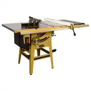
Page 8 - Features; Specifications
8 6.0 Features Figure 1 1 – Cast iron table extensions 2 – T-slots 3 – Transparent blade guard with riving knife 4 – Precision miter gauge with extension face 5 – Accu-Fence ® 6 – Rail set (30” shown) 7 – Blade tilt handwheel (with lock knob) 8 – Blade tilt angle scale 9 – Accu-Fence storage hook 10...
Page 10 - Setup and Assembly; Shipping contents
10 8.0 Setup and Assembly 8.1 Shipping contents (Figures 2 through 7) 1 Saw body with switch – A 2 Cast iron table extensions – B 1 Motor cover – C 2 Handwheels – D 2 Handwheel locking knobs – E 2 Handles – F 1 Arbor wrench – G 2 Open end wrenches (14-17, 10-12mm) – H 4 Hex keys (2.5/3/4/6mm) – I 1 ...
Page 11 - Unpacking and cleanup
11 Figure 6 Figure 7 – Stand hardware package (64B-SHP) 8.2 Unpacking and cleanup Open shipping container and check for shipping damage. Report any damage immediately to your distributor and shipping agent. Do not discard any shipping material until the Table Saw is assembled and running properly. C...
Page 12 - Stand assembly
12 8.3 Stand assembly Assembly tip: A ratchet wrench with sockets and extensions will speed assembly time. 1. Assemble stand, using Figure 8 as a guide. Use the provided carriage bolts, flat washers lock washers, and hex nuts (SHP-3/4/5/6). Only make fasteners snug at this time. They will be fully t...
Page 13 - Mounting saw to stand; Installing handwheels/hooks
13 Figure 9 8.4 Mounting saw to stand Refer to Figure 9 The table saw is heavy! Get persons to assist you in lifting it. Failure to comply may result in serious personal injury and/or damage to the machine. 1. Carefully lift table saw out of carton. 2. Place table saw atop the stand, orienting the m...
Page 14 - Installing table extensions; Leveling table extensions; Rails and Fence
14 8.6 Installing table extensions Refer to Figure 10. Figure 10 1. Attach a table extension to the saw table. Make sure edge bevel on table extension faces front, to match that of saw table. Use three screws, lock washers and flat washers (HP-1/2/3). Lightly snug screws with 17mm wrench. Assembly T...
Page 16 - Electrical connections; Grounding instructions
16 Figure 17 8.14 Riving knife Refer to Figure 18. The saw is supplied with two riving knives: One extends above the blade and accepts the blade guard; the other is a low-profile knife that acts alone for non-through cutting. To install a riving knife: 1. Remove table insert, and raise arbor all the...
Page 17 - Voltage conversion; Extension cords
17 If repair or replacement of the electric cord or plug is necessary, do not connect the equipment-grounding conductor to a live terminal. Use only 3-wire extension cords that have 3-prong grounding plugs and 3-pole receptacles that accept the tool's plug. Repair or replace damaged or worn cord imm...
Page 18 - Switch lockout; Adjustments; Fence alignment
18 9.4 Switch lockout The table saw is equipped with a push-button switch that will accept a safety padlock, as shown in Figure 20. To safeguard your machine from unauthorized operation and accidental starting by young children, the use of a padlock (not included) is highly recommended. Place the ke...
Page 19 - Positive blade stops
19 7. Loosen screw (F) and adjust indicator (G) until it reads 0º. 8. Tighten screw (F). NOTE: The bar of the miter gauge has two slots with set screws (H). Adjust these set screws (4mm hex key) to eliminate any play between bar and miter slot. Figure 22 10.4 Positive blade stops The stops for 90°, ...
Page 20 - Trunnion adjustment
20 Figure 26 10.5 Riving knife alignment The riving knife must be aligned with the blade for proper and safe operation of the table saw. This has been set by the manufacturer, but should be verified by the operator. 1. Disconnect machine from power source. 2. Install riving knife and tighten lever (...
Page 21 - Belt tension and replacement; Operations; Kickback prevention
21 Figure 29 Figure 30 5. Rotate marked tooth (A) so that it is slightly above table top at the rear and, using the square as before, verify that the distance to the blade is the same. See Figure 30. If the distances are not the same, make a careful note of the difference. 6. Loosen table screws (it...
Page 22 - Rip sawing
22 Releasing the workpiece before completing operation or not pushing work piece all the way past saw blade. Not using the splitter/riving knife when ripping or not maintaining alignment of the splitter/riving knife with the saw blade. Using a dull saw blade. Not maintaining alignment of the...
Page 23 - Resawing
23 Figure 34 The rip fence (A, Fig. 34) should be set for the width of the cut by using the scale on the front rail, or by measuring the distance between blade (A) and fence (B). Stand out of line with saw blade and workpiece to avoid sawdust and splinters coming off the blade or a potential kickbac...
Page 24 - Crosscutting; Bevel and miter operations
24 Figure 37 11.5 Crosscutting Crosscutting is where the workpiece is fed cross grain into the saw blade using the miter gauge to support and position the workpiece (Figure 38). Figure 38 Crosscutting should never be done freehand nor should the fence be used as an end stop unless an auxiliary block...
Page 25 - Dado cutting
25 Figure 41 Mitering – Crosscuts made at an angle to the edge of the workpiece are called miters (Figure 42). Set the miter gauge at the required angle, and make the cut the same as a normal crosscut except the workpiece must be held extra firmly to prevent creeping. Figure 42 Note : When making co...
Page 26 - Safety devices; Feather board; Push stick and push block
26 12.0 Safety devices Feather board Feather boards can be purchased at most tool stores, or made by the operator to suit particular applications. The feather board (Figure 44) should be made of straight grain hardwood approximately 1" thick and 4" to 8" wide depending on the size of the...
Page 27 - Maintenance; Cleaning
27 Figure 47 – Push stick template 13.0 Maintenance Always disconnect power to the machine before performing maintenance. Failure to do this may result in serious personal injury. Cleaning Clean the table saw according to the schedule below to ensure maximum performance. The schedule assumes the saw...
Page 28 - Optional accessories
28 14.0 Optional accessories These accessory items, purchased separately, can enhance the functionality of your table saw. Contact your dealer to order, or call Powermatic at the phone number on the cover. p/n 1791088 – Dado insert for 64B table saw p/n 708118 – Universal mobile base Figure 49
Page 30 - Replacement Parts; Table and Cabinet Assembly – Exploded View
30 16.0 Replacement Parts Replacement parts are listed on the following pages. To order parts or reach our service department, call 1-800-274-6848 Monday through Friday, 8:00 a.m. to 5:00 p.m. CST. Having the Model Number and Serial Number of your machine available when you call will allow us to ser...
Page 31 - Table and Cabinet Assembly – Parts List; Index No Part No
31 16.1.2 Table and Cabinet Assembly – Parts List Index No Part No Description Size Qty 1 ................ 64B-101 ..................... Table ........................................................................ ...................................... 1 2 ................ 64B-102 ...................
Page 32 - Motor and Trunnion Assembly – Exploded View
32 16.2.1 Motor and Trunnion Assembly – Exploded View
Page 33 - Motor and Trunnion Assembly – Parts List
33 16.2.2 Motor and Trunnion Assembly – Parts List Index No Part No Description Size Qty 1 ................ 64B-124 ..................... Lock Knob ................................................................ ...................................... 1 2 ................ 3520B-126 ....................
Page 36 - Blade Guard and Miter Gauge Assemblies – Exploded View
36 16.4.1 Blade Guard and Miter Gauge Assemblies – Exploded View
Page 37 - Blade Guard and Miter Gauge Assemblies – Parts List
37 16.4.2 Blade Guard and Miter Gauge Assemblies – Parts List Index No Part No Description Size Qty .................. 64B-BGA ................... Blade Guard Assembly (#1 thru 31) ........................ ...................................... 1 1 ................ 64B-401 ..................... Rivi...
Page 38 - Electrical Connections; Connections for 115 volt (64B Table Saw)
38 17.0 Electrical Connections 17.1 Connections for 115 volt (64B Table Saw) 115V 30uf 250 VAC 400MFD 125 VAC
Page 39 - Connections for 230 volt (64B Table Saw)
39 17.2 Connections for 230 volt (64B Table Saw) 230V 30uf 250 VAC 400MFD 125 VAC