Powermatic PM1-1791000KT - Manuals

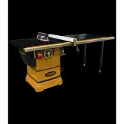
User Manual Powermatic PM1-1791000KT


Summary
2 1.0 Warranty and Service Powermatic warrants every product it sells against manufacturers’ defects. If one of our tools needs service or repair, please contact Technical Service by calling 1-800-274-6846, 8AM to 5PM CST, Monday through Friday. Warranty Period The general warranty lasts for the t...
3 2.0 Table of contents Section Page 1.0 Warranty and Service ..................................................................................................................................... 2 2.0 Table of contents ...............................................................................
3.0 Safety warnings 1. Read and understand the entire owner’s manual before attempting assembly or operation. 2. Read and understand the warnings posted on the machine and in this manual. Failure to comply with all of these warnings may cause serious injury. 3. Replace the warning labels if they bec...
Powermatic Table Saws Manuals
-
 Powermatic 1791285
User Manual
Powermatic 1791285
User Manual
-
 Powermatic 1791000K
User Manual
Powermatic 1791000K
User Manual
-
 Powermatic 1791000KT
User Manual
Powermatic 1791000KT
User Manual
-
 Powermatic 1791001K
User Manual
Powermatic 1791001K
User Manual
-
Powermatic 1791001KT
User Manual
-
 Powermatic 1791229K
User Manual
Powermatic 1791229K
User Manual
-
 Powermatic 1791230K
User Manual
Powermatic 1791230K
User Manual
-
 Powermatic PM1-1791001KT
User Manual
Powermatic PM1-1791001KT
User Manual
-
 Powermatic PM1-PM23130KT
User Manual
Powermatic PM1-PM23130KT
User Manual
-
 Powermatic PM1-PM23150KT
User Manual
Powermatic PM1-PM23150KT
User Manual
-
 Powermatic PM1-PM23150RKT
User Manual
Powermatic PM1-PM23150RKT
User Manual
-
 Powermatic PM1-PM23150WKT
User Manual
Powermatic PM1-PM23150WKT
User Manual
-
 Powermatic PM1-PM25130KT
User Manual
Powermatic PM1-PM25130KT
User Manual
-
 Powermatic PM1-PM25150KT
User Manual
Powermatic PM1-PM25150KT
User Manual
-
 Powermatic PM1-PM25150RKT
User Manual
Powermatic PM1-PM25150RKT
User Manual
-
 Powermatic PM1-PM25150WKT
User Manual
Powermatic PM1-PM25150WKT
User Manual
-
 Powermatic PM1-PM25330KT
User Manual
Powermatic PM1-PM25330KT
User Manual
-
 Powermatic PM1-PM25350KT
User Manual
Powermatic PM1-PM25350KT
User Manual
-
 Powermatic PM1-PM25350RKT
User Manual
Powermatic PM1-PM25350RKT
User Manual
-
 Powermatic PM1-PM25350WKT
User Manual
Powermatic PM1-PM25350WKT
User Manual