Pioneer DMH C5500NEX - User Manual

Pioneer DMH C5500NEX – User Manual, read for free online in PDF format. We hope this helps you resolve any issues you may have. If you have further questions, please contact us through the contact form.


Table of Contents:
- Page 2 – DASH DISASSEMBLY
- Page 3 – KIT PREPARATION
- Page 4 – radio brackets
- Page 5 – KIT ASSEMBLY; radio
- Page 9 – SALES; Toyota; Highlander; Without NAV; HARDWARE INCLUDED
Metra. The World’s Best Kits.
®
© COPYRIGHT 2019 METRA ELECTRONICS CORPORATION
REV. 11/25/19 INST108-TO3
I N S T A L L A T I O N I N S T R U C T I O N S
108-TO3
Attention!
Let the vehicle sit with the key
out of the ignition for a few minutes before
removing the factory radio. When testing the
aftermarket equipment, ensure that all factory
equipment is connected before cycling the
key to ignition.
Patent Pending
KIT FEATURES
• Designed specifically for the Pioneer DMH-C5500NEX 8-inch radio
• 108-TO3B = Black, 108-TO3BR = Brown
KIT COMPONENTS
• A) Radio trim panel • B) Radio brackets • C) Panel clips (4)
TOOLS REQUIRED
• Panel removal tool • Phillips screwdriver
• Cutting tool • 10mm socket wrench
TABLE OF CONTENTS
Dash Disassembly .................................................. 2
Kit Preparation ................................................... 3-4
Kit Assembly .......................................................... 5
WIRING & ANTENNA CONNECTIONS
(sold separately)
Wiring Harness: 70-1761 • TYTO-01 (w/ amp)
Antenna Adapter: Not required
A
B
C
Toyota
Highlander
(w/o NAV)
2008-2012
Visit
for more detailed information about the product and up-to-date vehicle
specific applications
"Loading the manual" means you need to wait until the file loads and becomes available for online reading. Some manuals are very large, and the time they take to appear depends on your internet speed.
Was this manual helpful?
About this manual
- Brand
- Pioneer
- Model
- DMH C5500NEX
- Document type
- User Manual
- Language(s)
- English
- Pages
- 9
- File size
- 1.4 MB
- Format
Other Manuals for Pioneer DMH C5500NEX
Summary
1.800.221.0932 | MetraOnline.com 2 1. Unclip and remove the a/c vent panel. (Figure A) 2. Unclip, unplug, and remove the climate control panel. (Figure B) 3. Remove (4) 10mm bolts securing the radio. Slide the radio out, then unplug and remove the radio/display assembly. (Figure C) Continue to Kit P...
REV. 11/25/2019 INST108-TO3 3 From the factory radio/display assembly:1. Remove (2) Phillips screws securing the display panel, then remove. (Figure A) 2. Unclip and remove the hazard switch assembly. (Figure B) 3. Remove (4) panel clips. (Figure C) Continued on the next page KIT PREPARATION (Figure...
1.800.221.0932 | MetraOnline.com 4 To the 108-TO3 radio housing:5. Secure the radio brackets to the factory display panel using the factory screws. (Figure D) 6. Clip in the hazard switch assembly. (Figure E) 7. Attach the (4) factory panel clips removed in step 3. (Figure E) Note: Panel clips have ...
Ask a question
Related manuals
Popular Pioneer Other
More Pioneer Other models
 Pioneer DMH 1500NEX User Manual
 Pioneer DMH 1770NEX User Manual
 Pioneer DMH 2000NEX User Manual
 Pioneer DMH 2600NEX User Manual
- Pioneer DMH 2660NEX User Manual
 Pioneer DMH C2550NEX User Manual
 Pioneer DMH T450EX User Manual
 Pioneer DMH W2770NEX User Manual
- Pioneer DMH W3000NEX User Manual
 Pioneer DMH W3050NEX User Manual
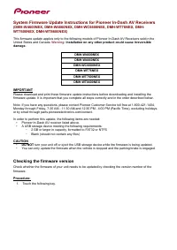 Pioneer DMH W4600NEX User Manual
- Pioneer DMH WC6600NEX User Manual