Page 2 - Contents
Contents 2 Warning and Safety instructions ...................................................................... 4 Caring for the environment .............................................................................. 14 Guide to the appliance .......................................................
Page 3 - Product data sheets
Contents 3 Worktop cutout – flush-fit .................................................................................... 54Spacer bars – flush-fit ......................................................................................... 57Installation dimensions – Flush-fit ..........................
Page 4 - Warning and Safety instructions
Warning and Safety instructions 4 This downdraft extractor complies with all relevant safety require-ments. Inappropriate use can, however, lead to personal injury andmaterial damage. Please read these operating and installation instructions carefullybefore using the downdraft extractor for the firs...
Page 5 - Correct application; This downdraft extractor is intended for use in domestic house-
Warning and Safety instructions 5 Correct application This downdraft extractor is intended for use in domestic house- holds and similar working and residential environments. The downdraft extractor is not suitable for outdoor use. It must only be used as a domestic appliance to extract vapours...
Page 6 - Safety with children
Warning and Safety instructions 6 Safety with children Children under 8 years of age must be kept away from the coun- tertop extractor unless they are constantly supervised. Children aged 8 and older may only use the countertop extractor without supervision if they have been shown how to use it ...
Page 7 - Technical safety; Unauthorised installation, maintenance and repairs can cause
Warning and Safety instructions 7 Technical safety Unauthorised installation, maintenance and repairs can cause considerable danger for the user. Installation, maintenance and re-pairs must only be carried out by a Miele authorised technician. The downdraft extractor must only be installed and o...
Page 9 - If the mains connection cable is damaged, it must be replaced
Warning and Safety instructions 9 If the mains connection cable is damaged, it must be replaced with a special mains connection cable by a qualified electrician (see“Electrical connection” in the “Installation” chapter). During installation, maintenance and repair work, the downdraft extractor m...
Page 10 - Danger of toxic fumes!
Warning and Safety instructions 10 Using at the same time as other heating appliances that depend on the airfrom the room Danger of toxic fumes! Great care should be taken when using the downdraft extractor inthe same room or the same area of the house as another heatingappliance that depends on t...
Page 12 - Correct use
Warning and Safety instructions 12 Correct use Open flames are a fire hazard. Never use an open flame beside the downdraft extractor. To avoidthe danger of fire, do not flambé or grill over an open flame. Whenswitched on, the downdraft extractor could draw flames into the fil-ter. Fat deposits cou...
Page 13 - Cleaning and care; The steam from a steam cleaning appliance could reach live elec-; Accessories; Only use genuine original Miele accessories and spare parts with
Warning and Safety instructions 13 Cleaning and care The steam from a steam cleaning appliance could reach live elec- trical components and cause a short circuit.Do not use a steam cleaner to clean the downdraft extractor. There is a risk of fire if the cooker hood is not cleaned as de- scribed ...
Page 14 - Caring for the environment
Caring for the environment 14 Disposal of the packing mater-ial The packaging is designed to protectthe appliance from damage duringtransportation. The packaging materialsused are selected from materials whichare environmentally friendly for disposaland should be recycled. Recycling the packaging re...
Page 15 - Guide to the appliance; Downdraft extractor; Extraction grille
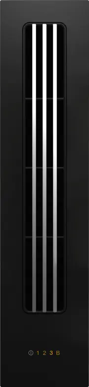
Guide to the appliance 15 Downdraft extractor a Extraction grille b Grease filter c Cover with control unit d Casing e Removable drip tray f Air duct(supplied as accessory) g FanIn the plinth on the floor h E-box
Page 16 - Controls and display; Countertop extractor On/Off
Guide to the appliance 16 Controls and display a Countertop extractor On/Off b Numerical displayTo set a power level
Page 17 - Accessories supplied; Air duct
Guide to the appliance 17 Accessories supplied The accessories supplied with your ap-pliance as well as a range of optionalones are available to order from Miele(see “Optional accessories”). Air duct Flat ducting system for routing air fromthe casing to the fan.
Page 18 - How it works; Extraction mode
How it works 18 Extraction mode The air is drawn in and cleaned by thegrease filter and directed outside. Recirculation mode (DUU 1000(-1) conversion kit required) The air is drawn in and cleaned by thegrease filter. The air is then directed intothe recirculation box where it is alsocleaned by the c...
Page 19 - Cleaning the SmartLine element for the first time
Cleaning the SmartLine element for the first time 19 Please stick the extra data plate forthe appliance supplied with this doc-umentation in the space provided inthe “After sales service” section ofthis booklet. Remove any protective wrapping andstickers. Clean the ceramic surface with adamp c...
Page 20 - Operation; Booster
Operation 20 Switching the downdraft ex-tractor on Insert the extraction grille. Touch the sensor control. The sensor controls light up. If no further entry is made, thedowndraft extractor will switch itselfoff after a few seconds. Setting/changing the powerlevel For light to heavy cooking va...
Page 21 - Tips on saving energy; - It is important to ensure that the kit-
Tips on saving energy 21 This downdraft extractor operates veryefficiently and economically. The follow-ing will help you to save even more en-ergy when using it: - It is important to ensure that the kit- chen is well ventilated during opera-tion. In extraction mode if there is in-sufficient air flo...
Page 22 - Unsuitable cleaning agents
Cleaning and care 22 Danger of burning due to hot surfaces.The surfaces will be hot after cook-ing.Switch the countertop extractor andthe cooking elements off.Allow the surfaces to cool down be-fore cleaning the countertop ex-tractor. Risk of damage due to moisture ingress.The steam from a steam...
Page 23 - Cleaning the ceramic surface; Risk of damage by pointed ob-; Cleaning the drip tray; Clean and dry the drip tray.
Cleaning and care 23 Cleaning the ceramic surface Risk of damage by pointed ob- jects.The seal between the SmartLine ele-ment and the worktop could sufferdamage.Do not use pointed objects for clean-ing. Not all soiling and residues can beremoved using a solution of wash-ing-up liquid. An invisible...
Page 24 - Grease filter/extraction grille; Risk of fire due to soiled grease
Cleaning and care 24 Grease filter/extraction grille The extraction grille and the reusablemetal grease filter in the vapour extrac-tion fan collect solid matter from kit-chen vapours (grease, dust, etc.) andtherefore prevent soiling of thedowndraft extractor. Accumulatedgrease solidifies over a lon...
Page 25 - Fitting the grease filter; Interior of the casing
Cleaning and care 25 Fitting the grease filter Fit the grease filter so that the straightside of the grease filter is on the sidethat connects to the air duct. Example: connector for air duct on theleft Interior of the casing When removing the grease filter forcleaning, also clean off any access...
Page 26 - Problem solving guide; Problem
Problem solving guide 26 Many malfunctions and faults that can occur in daily operation can be easilyremedied. Time and money will be saved because a service call will not beneeded. The following guide may help you to find the reason for a malfunction or a fault,and to correct it. Problem Cause and ...
Page 27 - Optional accessories; FlameGuard; Removes finger marks and light soiling
Optional accessories 27 Miele offer a comprehensive range ofuseful accessories as well as cleaningand conditioning products for yourMiele appliances. These products can be ordered throughthe Miele Webshop. They can also be ordered from Miele(see end of this booklet for contact de-tails) or from your...
Page 28 - After sales service; Contact in the event of a fault
After sales service 28 Contact in the event of a fault In the event of any faults which you cannot remedy yourself, please contact yourMiele dealer or the Miele Customer Service Department. You can book a Miele Customer Service Department call-out online atwww.miele.com/service. Contact information ...
Page 29 - Installation; Safety instructions for installation; Damage risk from incorrect installation.
Installation *INSTALLATION* 29 Safety instructions for installation Damage risk from incorrect installation. Incorrect installation can cause damage to the SmartLine element.The SmartLine element must only be installed by a qualified person. Damage from falling objects. Take care not to damage t...
Page 30 - Installation examples; Recirculation mode
Installation *INSTALLATION* 30 Installation examples Recirculation mode Extraction mode
Page 31 - Tiled worktop
Installation *INSTALLATION* 31 Installation notes – surface-mounted Sealing between the SmartLine Ele-ment and the worktop The SmartLine element and worktopmay be damaged if the elementneeds to be removed after it hasbeen sealed with a sealant.Do not use any sealant between theSmartLine element and ...
Page 32 - Worktop depth
Installation *INSTALLATION* 32 Installing severalSmartLine elements The gaps between the individual Smart-Line elements are sealed with a siliconesealant that is heat-resistant to at least160 °C. With flush-fit installation, thegap between the SmartLine element(s)and the worktop must also be sealedw...
Page 33 - Worktop cutout – surface-mounted
Installation *INSTALLATION* 33 Worktop cutout – surface-mounted
Page 34 - Installation with a countertop extractor
Installation *INSTALLATION* 34 Installation with a countertop extractor Combination examples Number x width [mm] Dimen- sion B [mm] Cooking ele- ments Countertop extractor 1 x 378 1 x 120 481 2 x 378 1 x 120 862 1 x 3781 x 620 2 x 120 1226 3 x 378 2 x 120 1365 2 x 3781 x 620 2 x 120 1607 4 x 378 2 x...
Page 35 - Installation without a countertop extractor
Installation *INSTALLATION* 35 Installation without a countertop extractor Combination examples Number x width [mm] Dimension B [mm] Cooking elements 1 x 378 359 2 x 378 740 1 x 3781 x 620 982 3 x 378 1121 2 x 3781 x 620 1363 4 x 378 1502 2 x 3781 x 800 1554 2 x 3781 x 936 1680
Page 36 - Spacer bars – surface-mounted; Installing 3 elements and 2 spacer bars; Spacer bars for the downdraft extractor – surface-mounted; Brackets
Installation *INSTALLATION* 36 Spacer bars – surface-mounted If you are installing several appliances, you must fit spacer bars between them. The clips supplied with the spacer bars are only required for installing aCSDA 700x FL. Installing 3 elements and 2 spacer bars Spacer bars for the downdraft ...
Page 37 - Installation dimensions – Surface-mounted; All dimensions are given in mm.
Installation *INSTALLATION* 37 Installation dimensions – Surface-mounted All dimensions are given in mm. a Front b FanIn the plinth on the floor c Air duct(supplied as accessory) d E-box
Page 38 - Side view
Installation *INSTALLATION* 38 Air duct dimensions – surface-mounted – worktop depth600 mm Side view
Page 40 - Front view
Installation *INSTALLATION* 40 Front view View from above
Page 41 - View from the side – right air duct connection
Installation *INSTALLATION* 41 Air duct dimensions – surface-mounted – worktop depth greaterthan 600 mm View from the side – right air duct connection
Page 42 - Duct connecter, adapted to the worktop depth
Installation *INSTALLATION* 42 a For maintenance work it must be possible to remove the rear cabinet wall.The cabinet wall and an adjoining room wall or a piece of furniture must be atleast 110 mm apart to ensure sufficient room for the ducting. b Duct connecter, adapted to the worktop depth c After...
Page 43 - View from the front – right air duct connection
Installation *INSTALLATION* 43 View from the front – right air duct connection View from above – right air duct connection
Page 44 - View from the front – left air duct connection
Installation *INSTALLATION* 44 If you want to install the air duct to the left of the downdraft extractor, the work-top must be at least 665 mm deep. View from the front – left air duct connection View from above – left air duct connection
Page 45 - Installation – surface-mounted; Worktop
Installation *INSTALLATION* 45 Installation – surface-mounted If the worktop is more than 24 mmdeep, it must be cut out underneathon the building-in side on the right orleft hand side. a Worktop b Maximum 24 mm c 12 mm Securing the brackets 1 bracket (supplied with the spacer bar)must be secured cen...
Page 46 - Seal any cut surfaces on
Installation *INSTALLATION* 46 Preparing the worktop Create the worktop cutout. Remem-ber to maintain the minimum safetydistances (see “Installation – Safetydistances”). Seal any cut surfaces on wooden worktops with a special varnish, sil- icone sealant or resin to prevent thewood from swelling ...
Page 47 - Installing the countertop extractor
Installation *INSTALLATION* 47 Installing the countertop extractor The countertop extractor can be in-stalled with the connector for the airduct on either the right or the left-handside. a Connector for air duct on the right b Connector for air duct on the left Stick the sealing strip supplied und...
Page 48 - Installing the air duct
Installation *INSTALLATION* 48 Installing the air duct Mount the air duct. If the exhaust ducting does not sit se-curely up against the exhaust ductconnection, stick the sealing stripsupplied to the exhaust duct connec-tion. Ensure that the air duct is not undermechanical tension after installat...
Page 49 - Installing the fan motor
Installation *INSTALLATION* 49 Length compensation – worktopdepth greater than 600 mm Divide the flat ducting into 2 pieces. 1piece must correspond to the differ-ence between 600 mm and the work-top depth. Insert the duct piece into the hori- zontal bend. Connect the duct piece with the ...
Page 50 - Mains connection cable
Installation *INSTALLATION* 50 E-box a Mains connection cable b Connection to window contact c Electrical connection socket for thefan operating voltage cable d Electrical connection socket for thefan control cable e Electrical connection socket for thecontrol unit cable Connection to window contact...
Page 51 - Sealing the gaps
Installation *INSTALLATION* 51 Loosen the lug and pull the plug out. Loosen the strain relief screw and unlock the casing on both sides . Open the casing. Remove the stopper. Exchange the bridge for the con- nection cable of the switching sys-tem. Close the casing. Tighten the...
Page 52 - Natural stone worktops
Installation *INSTALLATION* 52 Installation notes – flush-fit Flush-fit installation is only possible innatural stone (granite, marble), solidwood and tiled worktops. For installa-tion in worktops made of other materi-als, please consult the relevant manu-facturer as to whether their worktopsare sui...
Page 54 - Worktop cutout – flush-fit; Natural stone worktop
Installation *INSTALLATION* 54 Worktop cutout – flush-fit B 0 50 A 524 50 0 + 1 + 1 ß R 4 B A 0 2 12 0 1 0 5,5 + 0,5 * / 7 + 0,5 0 2 12 0 1 0 5,5 + 0,5 * / 7 + 0,5 + 1 + 1 + 1 + 1 B A + 1 + 1 Natural stone worktop Wooden worktop * 7 + 0.5 mm with CS 7611 FL
Page 57 - Spacer bars – flush-fit; Spacer bars for the downdraft extractor – flush-fit
Installation *INSTALLATION* 57 Spacer bars – flush-fit If you are installing several appliances, you must fit spacer bars between them. The clips supplied with the spacer bars are only required for installing aCSDA 700x FL. Installing 3 elements and 2 spacer bars Spacer bars for the downdraft extrac...
Page 58 - Installation dimensions – Flush-fit
Installation *INSTALLATION* 58 Installation dimensions – Flush-fit All dimensions are given in mm. a Front b FanIn the plinth on the floor c Stepped cutout (for detailed illustrations, see “Installation – Worktop cutout –flush-fit”) d 12 mm wooden frame (not supplied, for detailed illustrations, see...
Page 59 - Air duct dimensions – flush-fit – worktop depth 600 mm
Installation *INSTALLATION* 59 Air duct dimensions – flush-fit – worktop depth 600 mm Side view
Page 66 - Installation – flush-fit
Installation *INSTALLATION* 66 Installation – flush-fit If the worktop is more than 28 mmdeep, it must be cut out underneathon the building-in side on the right orleft hand side. a Worktop b Maximum 24 mm c 12 mm Securing the brackets 1 bracket (supplied with the spacer bar)must be secured centrally...
Page 73 - Ducting
Installation *INSTALLATION* 73 Ducting If the downdraft extractor is used at the same time as a heating appli-ance that relies on oxygen from thesame room, there is a risk of toxicfumes.It is essential that the “Warning andSafety” instructions are observed.The downdraft extractor should beinstalle...
Page 74 - Electrical connection; Risk of fire from overheating.
Installation *INSTALLATION* 74 Electrical connection The SmartLine element is supplied witha mains cable with moulded plug readyfor connection to a suitable earthedsocket. The socket must be easily accessibleafter the SmartLine element has beeninstalled. If the socket is not easily ac-cessible, ensu...
Page 75 - Data sheet for household cooker hoods
Product data sheets 75 The following data sheets apply to the models described in this operating instruc-tion manual. Data sheet for household cooker hoods In acc. with delegated regulation (EU) No. 65/2014 and regulation (EU) No.66/2014 MIELE Model name/identifier CSDA 7001 FL Annual Energy Consump...


 Miele WWD380 WCS PWash&Steam&9kg User Manual
 Miele W 1614 Manual
 Miele G 5266 SCVi SFP Active Plus User Manual
 Miele Classic C1 Turbo Team PowerLine - SBAN0 User Manual
![Miele PDR 307 [EL]](https://manualsarea.com/img/product/thumbs/48/ba/fd/bafde84806e8abc8b420f34eaf8fcd6e.webp) Miele PDR 307 [EL] User Manual
Miele PDR 307 [EL] User Manual Miele F 1911 Vi Manual
![Miele PDR 908 [EL MAR 3N AC 400V 50-60Hz]](https://manualsarea.com/img/product/thumbs/48/05/b7/05b705998b251f92b271e908423e1ecb.webp) Miele PDR 908 [EL MAR 3N AC 400V 50-60Hz] Installation Manual
Miele PDR 908 [EL MAR 3N AC 400V 50-60Hz] Installation Manual Miele K 9757 iD Manual


