Honeywell THM5421C1008 - Manual

Honeywell THM5421C1008 – Manual, read for free online in PDF format. We hope this helps you resolve any issues you may have. If you have further questions, please contact us through the contact form.


Table of Contents:
- Page 2 – SPECIFICATIONS
- Page 3 – IAQ Comfort System; FRONT VIEW
- Page 4 – INSTALLATION; CAUTION; Can cause electrical shock or equipment damage.
- Page 5 – Installing Equipment Interface Module (EIM); Communication LED; WIRING
- Page 6 – and cool system with single transformer
- Page 7 – Fig. 12. Typical hookup of conventional system with up to; dler for dehumidification with air conditioner and a; Fig. 17. Typical hookup of powered whole house; KEY
- Page 8 – Fig. 20. Hookup of Honeywell DH90 with fresh air intake for; POWER THE THERMOSTAT; Wiring 24 Vac Common
- Page 9 – Can cause erratic system operation.; IMPORTANT; Electrical Shock Hazard.
- Page 11 – ONE REMOTE INDOOR SENSOR INSTALLED (OPTIONAL); Install Discharge Air Temperature Sensor
- Page 12 – INSTALLER SETUP; Using Auto Discover
- Page 18 – INSTALLER SYSTEM TEST; Equipment Damage Hazard.; How to Use the Installer System Test; Fig. 28. Review thermostat buttons used during Installer
- Page 19 – Installer System Tests; OPERATION; Thermostat Keys
- Page 20 – System and Fan Settings; System; Control Humidification Level; WITH FROST PROTECTION; Control Dehumidification Level; With Air Conditioner
- Page 21 – DEHUMIDIFICATION DROOP CONTROL; With Whole House Dehumidifier; Ventilation Control; AUTOMATIC; HEAT PUMP OPERATION; Heat Pump LED Indication
- Page 22 – Heat Pump Emergency Heat LED Indication; AUXILIARY LOCKOUT FOR ELECTRIC HEAT BACKUP; Operation in Heat Mode
- Page 23 – Operation in Emergency Heat Mode
- Page 24 – Multi-Stage Heat and Cool Control; User Setup
- Page 25 – PROGRAMMING; Preprogrammed Energy Star Settings
- Page 26 – Sleep; Edit Schedule; to pick multiple days.; Cancel a Schedule Period
- Page 27 – Fan Schedule
- Page 28 – OPERATE VISIONPRO; Set Time; Set Temperature Overrides; PERMANENT HOLD
- Page 29 – SOUTHERN DEHUMIDIFICATION AWAY SETTING; Clean Thermostat Screen; Screen Locks; Partially Locked Screen; Humidification Control
- Page 30 – Filter Change Reminder
- Page 31 – Humidifier Pad Reminder; Temperature Recovery
- Page 32 – Inside Humidity Level
- Page 33 – Sensor; Operation
- Page 34 – Checkout; COMMUNICATION ERROR CODES
- Page 35 – TROUBLESHOOTING; Symptom
- Page 38 – COMPATIBILITY; Recommend the following products for use with the VisionPRO® IAQ.; Table 16. Humidifiers
- Page 40 – Automation and Control Solutions; Honeywell International Inc.
PRODUCT DATA
68-0287-1
VisionPRO
®
IAQ
Total Home Comfort System
APPLICATION
The VisionPRO
®
IAQ Total Home Comfort System features an
effortless, 7-Day programmable touchscreen thermostat that
provides control of temperature, humidification,
dehumidification, and ventilation.
FEATURES
• Large, clear display with backlight shows the current
and set temperature and time—even in the dark.
• Touchscreen interaction
• Real-time clock keeps time during power failures and
automatically updates to daylight savings.
• Change/check reminders let you know when to service
or replace filters.
• Various Hold options allow you to override the
program schedule, as desired.
• Controls humidification to increase homeowner
comfort while protecting woodwork and furnishings.
• Controls dehumidification using air conditioner with
high or low speed fan or a whole house dehumidifier.
• Controls ventilation with other HRV, ERV, or Freshair
damper. Vent on demand and automatically using
patented advanced ventilation control.
• Advanced heat pump control featuring balance point
plus 2°F droop to increase homeowner comfort.
Contents
Application/Features..........................................................
Specifications/Ordering Information ..................................
Installation ........................................................................
Wiring ...............................................................................
Power the Thermostat ......................................................
Installer Setup .................................................................. 12
Operation .......................................................................... 19
Programming .................................................................... 25
Troubleshooting ................................................................ 35
"Loading the manual" means you need to wait until the file loads and becomes available for online reading. Some manuals are very large, and the time they take to appear depends on your internet speed.
Was this manual helpful?
About this manual
- Brand
- Honeywell
- Model
- THM5421C1008
- Document type
- Manual
- Language(s)
- English
- Pages
- 40
- File size
- 3 MB
- Format
Summary
VISIONPRO ® IAQ TOTAL HOME COMFORT SYSTEM 68-0287—1 2 SPECIFICATIONS Thermostat Description: Electrical Ratings: Temperature Setting Range: Heating: 40°F to 90°F(4.5°C to 32°C). Cooling: 50°F to 99°F (10°C to 37°C). Operating Ambient Temperature: VisionPRO ® IAQ Thermostats: 0°F to 120°F (-18°C to 4...
VISIONPRO ® IAQ TOTAL HOME COMFORT SYSTEM 3 68-0287—1 Fig. 1. VisionPRO ® IAQ Comfort System dimensions in in. (mm). Fig. 2. THM5421C1008 Equipment Interface Module dimensions in in. (mm). Fig. 3. C7089U1006 Outdoor Sensor Mounting Clip dimensions in in. (mm). Fig. 4. 32003796-001 Cover Plate dimens...
VISIONPRO ® IAQ TOTAL HOME COMFORT SYSTEM 68-0287—1 4 Fig. 5. C7189U1005 Remote Indoor Sensor dimensions in in. (mm). INSTALLATION When Installing this Product... 1. Read these instructions carefully. Failure to follow the instructions can damage the product or cause a hazard- ous condition. 2. Chec...
Ask a question
Related manuals
Popular Honeywell Other
More Honeywell Other models
 Honeywell Thermostat T6069 User Manual
 Honeywell Thermostat T8411R User Manual
 Honeywell Thermostat TB6980 User Manual
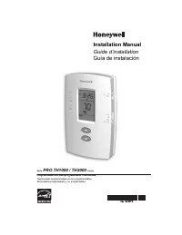 Honeywell Thermostat TH1000 User Manual
 Honeywell Thermostat TH6320WF User Manual
 Honeywell Thermostat TH8320WF User Manual
 Honeywell THM6000R Manual
 Honeywell Thor VM1 Manual
 Honeywell THP2400A1080 User Manual
 Honeywell THR872CUK Manual
 Honeywell THX321WF2003W Manual
 Honeywell THX321WFS2001W Manual