Honeywell 8635214 - User Manual
Honeywell 8635214 – User Manual, read for free online in PDF format. We hope this helps you resolve any issues you may have. If you have further questions, please contact us through the contact form.

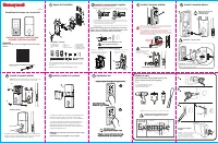
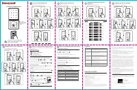


Table of Contents:
- Page 2 – PROGRAMMING RECORD; Lock
- Page 3 – L’emballage comprend :; Verrouillage électronique avec écran tactile; Testez la serrure; REMARQUE : Assurez-vous que le bouton est dans la bonne position.; Veuillez lire ce manuel avec soin avant; Ne serrez pas trop les vis du loquet.; GABARIT; Exemple; Outils nécessaires à la préparation de la porte; Avant d'ouvrir la porte
- Page 4 – REGISTRE DE PROGRAMMATION; Écran tactile pour réveiller la serrure
- Page 5 – Cerradura electrónica con pantalla táctil; Pruebe la cerradura; NOTA: Asegúrese de que la perilla esté en la posición correcta.; ¡Lea este manual cuidadosamente; No apriete excesivamente los tornillos del pasador.; PLANTILLA; Ejemplo; Herramientas necesarias para preparar la; Antes de abrir la puerta
- Page 6 – REGISTRO DE PROGRAMACIÓN
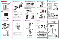
Latch
1 - Exterior Faceplate
1 - Interior Faceplate
1 - User Guide
2 - Keys
1 - Strike Plate
1 - Mounting Plate
1 - Latch
1 - 1 3/8” Screws
2 - Mounting Post
1 - Optional Set Screw
2 - 5/16” Screws
2 - 1” Screws
4 - 3/4” Screws
Read this manual carefully before installing and operating!
Please carefully check the above list to confirm all items have been received. If any items are
missing, please contact Consumer Assistance. (See page for contact information)
3/4
”
Screws
1
”
Screws
5/16
”
Screws
1 3/8
”
Screws
Optional
Set
Screw
Mounting
Post
Package Includes:
Exterior
Faceplate
User
Guide
Keys
Strike
plate
Interior
Faceplate Mounting
Plate
Electronic Deadolt with Touchscreen
Carefully insert control wire
into the wire connector
Work with the door open
NOTE: Make sure the connector dots
line up with the dots on the controle wire
Test the lock
Lock and unlock using the thumb knob make sure the latch is opening and
closing easily. If not, go back to step 2 and ensure you followed the steps
NOTE: Make sure the Knob is in the correct position.
Be careful not to pinch the control wire when assembling
This Electronic lock requires (4) High Quality AA Alkaline
batteries. When all 4 batteries are installed in the correct
position, you should hear 2 beeps and the keypad will
illuminate.
The Lock motor will engage and do a series of locking and
unlocking motions in order to automatically determine your
door “Handing” (left or right handed door). The lock will beep
and the touchscreen will flash signaling success.
NOTE: Do not touch the touchscreen until the light turns off.
Do not use rechargeable batteries or non-alkaline batteries.
VERTICAL
POSITION
1
Read this manual carefully before
installing and operating!
7
Testing Operation
2
2-3/4” position
E
2-3/8” position
NOTE: Do not extend Cylindrical Cover past 2-3/4” (70mm).
E
K
J
M
B
C
C
Install Enclosed Latch and Strike Plate.
Do not over-tighten latch screws.
Deadbolt Latch Must Be
Retracted During Installation.
TO CONVERT FROM 2-3/8” (60mm) BACKSET TO 2-3/4” (70mm) BACKSET:
1. Hold latch with numbers facing forward and thumb pressing on the bolt.
2. Rotate the cylinder cover clockwise.
3. Pull and twist the extension plate all the way out.
4. Rotate the cylinder counter clockwise so that the marking aligns with
the 2-3/4” position indicator.
Refer to Template included
for Door Prep Instructions
NOTE: Skip this step if your door comes with pre-drilled holes.
Example
Preparing Door
Installation Overview
Screw Mounting Post (M)
into holes on Mounting Plate (C).
(L) screw goes into the door to
prevent the lock from shifting and
is optional.
4
Install Interior Assembly
Work with the door open
Important
Use the QR code below for the most up to date instructions:
6
B
J
B
H
C
Install Batteries and Cover
5
Install Interior Assembly
3
Check that the Rubber Gasket is secured on the Exterior Assembly. Insert the
Exterior Assembly onto the door with the tailpiece going through the Deadbolt
Latch Set in the
VERTICAL POSITION
.
Route the Control Wire through the door
UNDER
the Deadbolt Latch Set.
Make
sure the door is shut, lock and unlock using the key, ensure that the latch is
operating smoothly and is aligned properly without scraping the strike plate.
If not, go back to step 2 and ensure you followed the steps
Install Exterior Assembly
Secure mounting plate to door
L
(optional)
I
C
Remove (J) Screw from inside
the battery compartment within the
(B) Housing to release the Mounting
Plate (C).
• Drill
• 2 1/8” Hole Saw
• 1” Hole Saw
• 3/4” Chisel
Tools Needed for Door Preparation (if
there is no knob hole):
• Phillips Screwdriver
Tools Needed for Lock Installation:
Preparation for Interior Assembly.
The latch plate on the door needs to be straight and not protruding
from door. Make adjustment before installing or this will cause
problems with bolt fitting into latch hole.
ENGLISH
2 1/8” Hole Saw
J
F
Strike Plate Installation
NOTE: The strike plate on the door frame
needs to be straight and not protruding from
door frame. Make adjustment before installing
or this will cause problems with bolt
fitting into latch hole.
1” Hole Saw
1.
2.
3.
4.
"Loading the manual" means you need to wait until the file loads and becomes available for online reading. Some manuals are very large, and the time they take to appear depends on your internet speed.
Summary
Programming Instructions Complete all the programming steps in the programming mode within 5 seconds Do not press keypad until keypad stops illuminating Light bar indicates Green with latch open Red when latch is locked. Creating Administrator Code 11 Input 6 digit code, Press Press Press 4 Repeat t...
Verrou 1 - Plaquette extérieure1 - Plaquette intérieure 1 - Guide de l’utilisateur2 - Clés 1 - Gâche 1 - Plaque support1 - Verrou 1 - Vis de 35 mm (1-3/8 po) 2 - Montant/tige de montage1 - Vis de réglage en option 2 - Vis de 8 mm (5/16 po) 2 - Vis de 25 mm (1 po) 4 - Vis de 19 mm (3/4 po) Veuillez l...
Instructions de programmation Complétez toutes les étapes de programmation dans les 5 secondes. Ne pas appuyer sur le clavier jusqu'à ce qu'il s'arrête de clignoter La barre lumineuse indique en vert lorsque le verrou est ouvert en rouge lorsque le verrou est verrouillé. Créer un code d'Administrate...