Page 2 - English; TablE Of COnTEnTS; PaGE
1 English TablE Of COnTEnTS PaGE SafETY PRECaUTIOnS ............................................................................. 2 Electrical Requirements .............................................................................. 3 before Using Your Microwave Oven .................................
Page 3 - SafETY PRECaUTIOnS; Warning! – To reduce the risk of fire, electric shock, or injury to
Thank you for using our Haier product. This easy-to-use manual will guide you in getting the best performance from your Haier Microwave Oven.Remember to record the model and serial number. They are on a label in the Microwave Oven. Model number Serial number Date of purchase English 2 SafETY PRECaUT...
Page 4 - ElECTRICal REQUIREMEnTS
3 English ElECTRICal REQUIREMEnTS Product rating is 120 volts aC, 60 Hertz and 1550 watts. This product must be connected to a supply circuit of the proper voltage and frequency.Wire size must conform to the requirements of the national Electrical Code or the prevailing local code for this kilowatt ...
Page 5 - bEfORE USInG YOUR MICROWaVE OVEn; DANGER; YOU Can SERIOUSlY InjURED If YOU; IMPORTANT: READ AND sAvE THEsE INsTRUcTIONs
4 English bEfORE USInG YOUR MICROWaVE OVEn YOU Can bE SERIOUSlY InjURED If YOU DO nOT fOllOW InSTRUCTIOnS IMMEDIaTElY. DANGER WARNING YOU Can SERIOUSlY InjURED If YOU DO nOT fOllOW InSTRUCTIOnS. all safety messages will tell you what the potential hazard is, how to reduce the chance of injury and wh...
Page 6 - HOOD ExHaUST
English 5 English HOOD ExHaUST nOTE: Read these next two pages only if you plan to vent your exhaust to the outside. If you plan to recirculate the air back into the room, proceed to page 7. OUTsIDE TOP EXHAUsT (EXAMPLE ONLY) The following chart describes an example of one possible ductwork installa...
Page 7 - dampers swing freely and nothing is blocking the ducts.; Do not use less than a; MAXIMUM DUcT LENGTH:; should not exceed 120 equivalent feet
English 6 English nOTE: If you need to install ducts, note that the total duct length of 31⁄4” x 10” (8.2 x 25.4 cm) rectangular or 6” (15.2 cm) diameter round duct should not exceed 120 equivalent feet (36.5 m). Outside ventilation requires a HOOD ExHaUST DUCT. Read the following carefully. nOTE: I...
Page 8 - DaMaGE—SHIPMEnT/InSTallaTIOn; HARDWARE PAcKET; have
English 7 English DaMaGE—SHIPMEnT/InSTallaTIOn PaRTS InClUDED • If the unit is damaged in shipment, return the unit to the store in which it was bought for repair or replacement.• If the unit is damaged by the customer, repair or replacement is the responsibility of the customer.• If the unit is dam...
Page 9 - TOOlS anD MaTERIalS nEEDED
English 8 English TOOlS anD MaTERIalS nEEDED MOUnTInG SPaCE # 1 Phillips screwdriver Pencil Ruler or tape measure and straight edge Carpenter square (optional) Tin snips (for cutting damper, if required) Hammer (optional) Stud finder or Filler blocks or scrap wood pieces, if needed for top cabinet s...
Page 10 - PlaCEMEnT Of THE MOUnTInG PlaTE; A. REMOvING THE MIcROWAvE OvEN FROM THE cARTON/; OR
9 English 1. PlaCEMEnT Of THE MOUnTInG PlaTE A. REMOvING THE MIcROWAvE OvEN FROM THE cARTON/ REMOvING THE MOUNTING PLATE B. FINDING THE WALL sTUDs 1. Remove the installation instructions, filters, glass tray and the small hardware bag. Do not remove the Styrofoam protecting the front of the oven.2. ...
Page 11 - c. DETERMINING WALL PLATE LOcATION UNDER YOUR; THE MICROWAVE MUST BE LEVEL.; Use a level to make sure the cabinet bottom is level.
10 English c. DETERMINING WALL PLATE LOcATION UNDER YOUR cABINET. PLATE POSITION—BENEATH fLAT BOTTOM CABINET PLATE POSITION—BENEATH RECESSED BOTTOM CABINET WITH fRONT OVERHANg PLATE POSITION—BENEATH fRAMED RECESSED CABINET BOTTOM Mounting Plate Tabs Touching the Cabinet Bottom At least 30 ʺ (76.2 cm...
Page 12 - Wear gloves to avoid cutting fingers on sharp edges.; D. ALIGNING THE WALL PLATE; Use the mounting plate; as the template; for the rear wall. Place the mounting; touching the bottom of the; If neither C nor D is in a stud, find a stud somewhere in area E and; Set the mounting plate aside.
CAUTION: Wear gloves to avoid cutting fingers on sharp edges. 11 English D. ALIGNING THE WALL PLATE Draw a vertical line on the wall at the center of the 30” (76.2 cm) wide space. 1. Use the mounting plate 2. as the template for the rear wall. Place the mounting plate on the wall, making sure that t...
Page 13 - On models shipped for
12 English This microwave oven is designed for adaptation to the following three types of ventilation: A. Outside Top Exhaust (Vertical Duct) B. Outside Back Exhaust (Horizontal Duct) C. Recirculating (Non-Vented Ductless)If direct-wiring microwaveNOTE: This microwave is shipped assembled for Recirc...
Page 14 - INsTALLATION OvERvIEW; a. OUTSIDE TOP ExHaUST
13 English INsTALLATION OvERvIEW a1. attach Mounting Plate to Wall a2. Prepare Top Cabinet a3. adapting Microwave blower for Outside Top Exhaust a4. Check Damper Operation a5. Mount Microwave Oven a6. adjust Exhaust adaptor a7. Connect Ductwork attach the plate to the wall using toggle bolts. at lea...
Page 15 - A2. UsE TOP cABINET TEMPLATE FOR PREPARATION OF
14 English You need to drill holes for the top support screws, a hole large enough for the power cord to fit through, and a cutout large enough for the exhaust adaptor.• Read the instructions on the TOP CabInET TEMPlaTE.• Tape it underneath the top cabinet.• Drill the holes, following the instructio...
Page 16 - IMPORTANT: Do not grip or use handle; A3. ADAPTING MIcROWAvE BLOWER FOR OUTsIDE
English fOR EaSIER InSTallaTIOn anD PERSOnal SafETY, WE RECOMMEnD THaT TWO PEOPlE InSTall THIS MICROWaVE OVEn. 15 English 4. Place the blower unit back into the opening. 5. Secure blower unit to microwave with the screw removed in Step 1. Make sure the screw is tight. 6. Replace blower plate with th...
Page 17 - A5. MOUNT THE MIcROWAvE OvEN
English 16 English lift microwave, tilt it forward, and hook slots 1. at back bottom edge onto four lower tabs of mounting plate. Rotate front of oven up against cabinet 2. bottom. Insert a self-aligning screw through top 3. center cabinet hole. Temporarily secure the oven by turning the screw at le...
Page 18 - b. OUTSIDE baCk ExHaUST
English 17 English INsTALLATION OvERvIEW b1. Prepare Rear Wall b2. Remove blower Plate b3. attach Mounting Plate to Wall b4. Prepare Top Cabinet b5. adjust blower b6. Mount the Microwave Oven You need to cut an opening in the rear wall for outside exhaust. Read the instructions on the REaR • Wall TE...
Page 19 - B3. ATTAcH THE MOUNTING PLATE TO THE WALL
English 18 English attach the plate to the wall using toggle bolts. at least one wood screw must be used to attach the plate to a wall stud. Remove the toggle wings from the bolts. 1. Insert the bolts into the mounting plate 2. through the holes designated to go into drywall and reattach the toggle ...
Page 20 - B5. ADAPTING MIcROWAvE BLOWER FOR OUTsIDE BAcK; NOTE: The blower unit exhaust
English B5. ADAPTING MIcROWAvE BLOWER FOR OUTsIDE BAcK EXHAUsT Remove and save screw that holds 1. blower motor to microwave. Carefully pull out the blower unit. The 2. wires will extend far enough to allow you to adjust the blower unit. Roll the blower unit 90° 3. 5. Gently remove the wires from th...
Page 21 - B6. MOUNT THE MIcROWAvE OvEN
English 10. attach the exhaust adaptor to the rear of the oven by sliding it into the guides at the top center of the back of the oven. Push in securely until it is in the lower locking tabs. Take care to assure that the damper hinge is installed so that it is at the top and that the damper swings f...
Page 24 - c2. UsE TOP cABINET TEMPLATE FOR PREPARATION OF; c4. MOUNT THE MIcROWAvE OvEN
English You need to drill holes for the top support screws, a hole large enough for the power cord to fit through. Read the instructions on the TOP • CabInET TEMPlaTE. Tape it underneath the top cabinet. • Drill the holes, following the instructions • on the TOP CabInET TEMPlaTE. Place the microwave...
Page 25 - c5. INsTALLING OR cHANGE THE cHARcOAL FILTER
English NOTE: The charcoal filter is factory installed. follow these steps to replace a filter or to install a filter after converting a vented model to recirculating operation. c5. INsTALLING OR cHANGE THE cHARcOAL FILTER Remove screws on top of grille using a 1. #1 Phillips screwdriver. Open the d...
Page 26 - français; TablE DES MaTIERES
English 1 français TablE DES MaTIERES PaGE MESURES DE SÉCURITÉ............................................................................. 2 Exigences Électriques ................................................................................ 3 avant D’utiliser Votre four À Micro-Ondes ..............
Page 27 - MESURES DE SÉCURITÉ; Avertissement! – Pour réduire les risques d’incendie, de choc; les lave-vaisselle, et les garder hors de la portée des enfants.; vous en aurez besoin pour obtenir un service de garantie.
English français 2 MESURES DE SÉCURITÉ Avertissement! – Pour réduire les risques d’incendie, de choc électrique ou de blessures, il faut toujours exercer des mesures de sécurité de base, incluant celles qui suivent : 1. lire toutes les instructions avant l’utilisation de l’appareil.2. Utiliser le la...
Page 28 - ExIGEnCES ÉlECTRIQUES
3 ExIGEnCES ÉlECTRIQUES les caractéristiques nominales de ce produit sont : 120 V Ca, 60 Hz et 1550 W. Ce produit doit être branché à un circuit d’alimentation de tension et de fréquence appropriées. la grosseur des fils doit être conforme aux exigences du Code national d’électricité ou du code loca...
Page 29 - aVanT D’UTIlISER VOTRE fOUR; VOUS RISQUEz D’ÊTRE GRaVEMEnT blESSÉ SI; comment réduire les risques de blessures et ce qu’il peut arriver; IMPORTANT : LIRE ET cONsERvER cEs INsTRUcTIONs; • vous aidera à l’avenir si vous avez des questions.
4 français aVanT D’UTIlISER VOTRE fOUR À MICRO-OnDES VOUS RISQUEz D’ÊTRE GRaVEMEnT blESSÉ SI VOUS nE SUIVEz PaS CES InSTRUCTIOnS IMMÉDIaTEMEnT. DANGER WARNING VOUS RISQUEz D’ÊTRE GRaVEMEnT blESSÉ SI VOUS nE SUIVEz PaS CES InSTRUCTIOnS. Tous les messages de sécurité vous informeront du danger potenti...
Page 30 - ÉVaCUaTIOn DE la HOTTE; ÉvAcUATION À L’EXTÉRIEUR PAR LE DEssUs (EXEMPLE sEULEMENT); ÉvAcUATION À L’EXTÉRIEUR PAR L’ARRIÈRE (EXEMPLE sEULEMENT); le tableau suivant décrit un exemple d’installation de conduit.
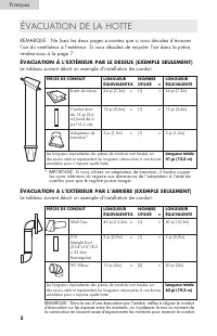
5 ÉVaCUaTIOn DE la HOTTE REMaRQUE : ne lisez les deux pages suivantes que si vous décidez d’évacuer l’air du ventilateur à l’extérieur. Si vous décidez de recycler l’air dans la pièce, rendez-vous à la page 7. ÉvAcUATION À L’EXTÉRIEUR PAR LE DEssUs (EXEMPLE sEULEMENT) le tableau suivant décrit un ex...
Page 31 - cONNEXION AU cONDUIT:; N’utilisez pas un conduit dont le; LONGUEUR MAXIMALE DU
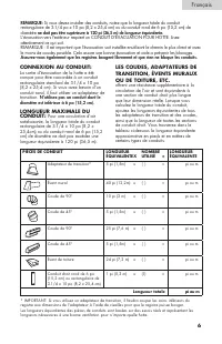
6 REMARQUE: Si vous devez installer des conduits, notez que la longueur totale du conduit rectangulaire de 3-1/4 po x 10 po (8,2 x 25,4 cm) ou du conduit rond de 6 po (15,2 cm) de diamètre ne doit pas être supérieure à 120 pi (36,5 m) de longueur équivalente. l’évacuation vers l’extérieur requiert u...
Page 32 - d’une entente entre le client et l’installateur.; sAcHET DE QUINcAILLERIE
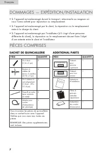
7 DOMMaGES — ExPÉDITIOn/InSTallaTIOn PIèCES COMPRISES • Si l’appareil est endommagé durant le transport, retournez-le au magasin où vous l’avez acheté pour réparation ou remplacement.• Si l’appareil est endommagé par le client, la réparation ou le remplacement reste à la charge du client.• Si l’appa...
Page 33 - supérieure concernant le dégagement du cordon d’alimentation.
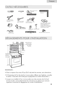
8 OUTIlS nÉCESSaIRES DÉGaGEMEnTS POUR l’InSTallaTIOn Tournevis Phillips n o 1 Règle ou ruban à mesureret règle droite Équerre de menuisier(facultative) Cisailles de ferblantier(pour couper le registre,si nécessaire) Ciseaux (pour couper legabarit, si nécessaire) Perceuse électrique avec foretsde 3/1...
Page 34 - InSTallaTIOn DE la PlaQUE DE MOnTaGE; ENLÈvEMENT DE LA PLAQUE DE MONTAGE; OU; LE fOUR À MICRO-ONDES DOIT
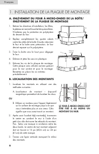
9 1. InSTallaTIOn DE la PlaQUE DE MOnTaGE A. ENLÈvEMENT DU FOUR À MIcRO-ONDEs DE LA BOÎTE/ ENLÈvEMENT DE LA PLAQUE DE MONTAGE B. LOcALIsATION DEs MONTANTs 1. Retirez les directives d’installation, les filtres, le plateau en verre et le sachet de quincaillerie. n’enlevez pas la protection en polystyr...
Page 35 - micro-ondes et pour vous assurer qu’il est de niveau.; LE fOUR À MICRO-ONDES DOIT ÊTRE DE NIVEAU.; Utilisez un niveau pour vous assurer
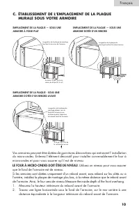
10 c. ÉTABLIssEMENT DE L’EMPLAcEMENT DE LA PLAQUE MURALE sOUs vOTRE ARMOIRE EMPLACEMENT DE LA PLAQUE — SOUS UNE ARMOIRE À fOND PLAT EMPLACEMENT DE LA PLAQUE - SOUS UNE ARMOIRE DOTÉE D’UN REBORD AVANT EMPLACEMENT DE LA PLAQUE — SOUS UNE ARMOIRE DOTÉE D’UN REBORD Languettes de la plaque de montagetouc...
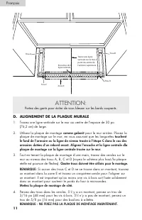
Page 36 - D. ALIGNEMENT DE LA PLAQUE MURALE; Tracez une ligne verticale sur le mur au centre de l’espace de 30 po
ATTENTION: Portez des gants pour éviter de vous blesser sur les bords coupants. 11 D. ALIGNEMENT DE LA PLAQUE MURALE Tracez une ligne verticale sur le mur au centre de l’espace de 30 po 1. (76,2 cm) de large.Utilisez la plaque de montage 2. comme gabarit pour le mur arrière. Placez la plaque de mont...
Page 37 - TYPES D’InSTallaTIOn; A. ÉvAcUATION À L’EXTÉRIEUR PAR LE DEssUs; Consultez la page 13
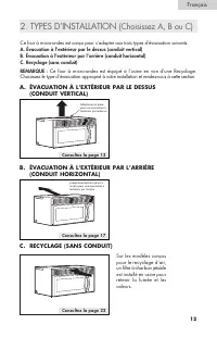
12 Ce four à micro-ondes est conçu pour s’adapter aux trois types d’évacuation suivants: A. Évacuation à l’extérieur par le dessus (conduit vertical)B. Évacuation à l’extérieur par l’arrière (conduit horizontal)C. Recyclage (sans conduit)REMARQUE : Ce four à micro-ondes est équipé à l’usine en vue d...
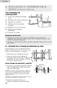
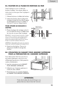
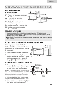
Page 38 - POUR UTILIsER LEs BOULONs À AILETTEs:; A1. FIXATION DE LA PLAQUE DE MONTAGE AU MUR; REMARQUES IMPORTANTES :; a. ÉVaCUaTIOn À l’ExTÉRIEUR PaR lE; COnDUIT VERTICal
13 vUE D’ENsEMBLE DE L’INsTALLATION a1. fixation de la plaque de montage au mur a2. Préparation de l’armoire supérieure a3. ajustement du ventilateur a4. Vérification du fonctionnement du registre a5. Installation du four à micro-ondes a6. ajustement de l’adaptateur d’évacuation a7. Connexion au con...
Page 39 - A2. UTILIsATION DU GABARIT POUR ARMOIRE sUPÉRIEURE
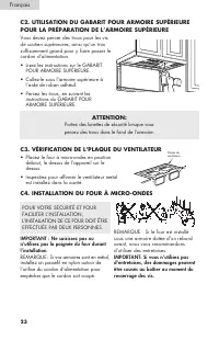
14 Vous devez percer des trous pour les vis de soutien supérieures, ainsi qu’un trou suffisamment grand pour y faire passer le cordon d’alimentation et une ouverture assez grande pour l’adaptateur d’évacuation.• Lisez les instructions sur le GABARIT POUR aRMOIRE SUPÉRIEURE.• Collez-le sous l’armoire...
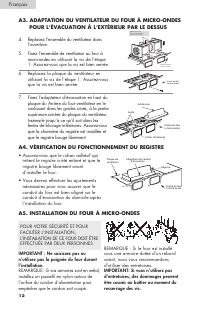
Page 40 - A3. ADAPTATION DU vENTILATEUR DU FOUR À MIcRO-ONDEs
POUR VOTRE SÉCURITÉ ET POUR faCIlITER l’InSTallaTIOn, l’InSTallaTIOn DE CE fOUR DOIT ÊTRE EffECTUÉE PaR DEUx PERSOnnES. 15 4. Replacez l’ensemble du ventilateur dans l’ouverture. 5. fixez l’ensemble de ventilateur au four à micro-ondes en utilisant la vis de l’étape 1. assurez-vous que la vis est bi...
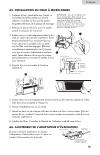
Page 41 - A6. AJUsTEMENT DE L’ADAPTATEUR D’ÉvAcUATION
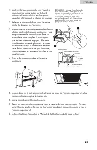
16 Soulevez le four, penchez-le vers l’avant, et 1. accrochez les fentes situées sur le bord inférieur à l’arrière du four sur les quatre languettes inférieures de la plaque de montage. Relevez le devant du four pour le mettre 2. contre le dessous de l’armoire. Insérez une vis à auto-alignement dans...
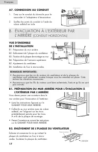
Page 42 - REMARQUES IMPORTANTES:; b. ÉVaCUaTIOn À l’ExTÉRIEUR PaR; COnDUIT HORIzOnTal
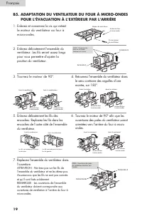
17 vUE D’ENsEMBLE DE L’INsTALLATION b1. Préparation du mur arrière b2. Enlèvement de l’plaque du ventilateur b3. fixation de la plaque de montage au mur b4. Préparation de l’armoire supérieure b5. ajustement du ventilateur b6. Installation du four à micro-ondes Vous devez percer une ouverture dans l...
Page 45 - IMPORTANT : Ne saisissez pas ou
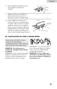
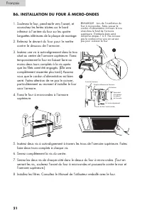
8. fixez l’ensemble de ventilateur au four à micro-ondes en utilisant la vis d’origine. 9. Replacez la plaque du ventilateur au même endroit qu’avant avec la vis. assurez-vous que la vis est bien serrée. 10. fixez l’adaptateur d’évacuation à l’arrière du four en le coulissant dans les guides situés ...
Page 50 - c5. INsTALLATION OU cHANGEMEUT DU FILTRE À cHARBON
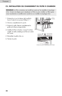
REMARQUE: le filtre à charbon est installé en usine sur les modèles à recyclage d’air. Suivez ces étapes pour remplacer un filtre ou pour installer un filtre après avoir transformé un modèle avec conduit en un modèle à recyclage d’air. c5. INsTALLATION OU cHANGEMEUT DU FILTRE À cHARBON Enlevez les v...
Page 51 - COnTEnIDOS
1 COnTEnIDOS PaGE PRECaUCIOnES DE SEGURIDaD ............................................................. 2 Requisitos eléctricos ................................................................................ 3 antes de utilizar su horno microondas ....................................................
Page 52 - PRECaUCIOnES DE SEGURIDaD; ¡Advertencia! – Para reducir el riesgo de incendio, descarga; Español
Gracias por usar nuestro producto Haier. Este manual fácil de usar le guiará para obtener el mejor rendimiento posible de su horno microondas Haier.Recuerde anotar los números de modelo y de serie. Están en una etiqueta en el horno microondas. número de modelo número de serie fecha de compra 2 PRECa...
Page 53 - REQUISITOS ElÉCTRICOS; código local que prevalezca.
3 REQUISITOS ElÉCTRICOS la clasificación del producto es 120 voltios de Ca, 60 Hertz y 1550 vatios. Este producto debe conectarse en un circuito de suministro con el voltaje y la frecuencia correctos.El tamaño del cable debe cumplir los requerimientos del Código Eléctrico nacional o el código local ...
Page 54 - PELIGRO; PUEDE RESUlTaR SERIaMEnTE HERIDO SI; IMPORTANTE: LEA EsTAs INsTRUccIONEs Y cONsÉRvELAs
4 anTES DE UTIlIzaR SU HORnO MICROOnDa PUEDE RESUlTaR SERIaMEnTE HERIDO SI nO SIGUE laS InSTRUCCIOnES DE InMEDIaTO. PELIGRO ADvERTENcIA PUEDE RESUlTaR SERIaMEnTE HERIDO SI nO SIGUE laS InSTRUCCIOnES. Todos los mensajes de seguridad le informarán cuál es el riesgo potencial, cómo reducir las posibili...
Page 55 - CaMPana DE SalIDa DE EManaCIOnES; nuevamente en la habitación, siga en la página 7.; sALIDA sUPERIOR DE EMANAcIONEs HAcIA EL EXTERIOR (sOLO EJEMPLO)
5 CaMPana DE SalIDa DE EManaCIOnES nOTa: lea estas páginas a continuación únicamente si planifica realizar la salida de emanaciones hacia el exterior. Si tiene pensado recircular el aire nuevamente en la habitación, siga en la página 7. sALIDA sUPERIOR DE EMANAcIONEs HAcIA EL EXTERIOR (sOLO EJEMPLO)...
Page 56 - Además, asegúrese de que los; cONEXIÓN DE LA sALIDA DE; No utilice un conducto de menos; LARGO MÁXIMO DEL cONDUcTO:
6 nOTa: Si necesita instalar conductos, tenga en cuenta que el largo total del conducto rectangular de 31⁄4” x 10” (8,2 x 25,4 cm) o circular de 6” (15,2 cm) de diámetro no debe superar los 120 pies equivalentes (36,5 m). Para la ventilación exterior es necesario un COnDUCTO PaRa la CaMPana DE SalID...
Page 57 - PAQUETE cON PIEZAs
7 DaÑOS DURanTE El EnVÍO O la InSTalaCIón PIEzaS InClUIDaS Si la unidad resulta dañada durante el envío, devuélvala a la tienda en la • que la compró para que le realicen reparaciones o la reemplacen.Si la unidad fue dañada por el cliente, las reparaciones o el reemplazo son • responsabilidad del cl...
Page 59 - UbICaCIón DE la PlaCa DE MOnTajE; A. cÓMO QUITAR EL HORNO MIcROONDAs DE LA cAJA/; EL MIcROONDAs DEBE EsTAR cONEcTADO AL MENOs A UN MON-
9 1. UbICaCIón DE la PlaCa DE MOnTajE A. cÓMO QUITAR EL HORNO MIcROONDAs DE LA cAJA/ cÓMO QUITAR LA PLAcA DE MONTAJE B. cÓMO ENcONTRAR LOs MONTANTEs DE LA PARED 1. Retire las instrucciones de instalación, los filtros, la bandeja de vidrio y la bolsa pequeña con piezas complementarias. no quite la es...
Page 60 - EL MICROONDAS DEBE ESTAR NIVELADO.; Use un nivel para asegurarse de que la
10 c. cÓMO DETERMINAR LA UBIcAcIÓN DE LA PLAcA DE LA PARED DEBAJO DE sU GABINETE. POSICIÓN DE LA PLACA, DEBAJO DE LA PARTE INfERIOR PLANA DEL gABINETE UBICACIÓN DE LA PLACA, DEBAJO DEL gABINETE EMPOTRADO INfERIOR CON SALIENTE fRONTAL POSICIÓN DE LA PLACA, DEBAJO DEL gABINETE EMPOTRADO INfERIOR Las l...
Page 61 - Use guantes para evitar cortarse los dedos con los bordes filosos.; D. ALINEAcIÓN DE LA PLAcA PARA LA PARED; Trace una línea vertical en la pared en el centro de las 30” (76,2 cm) del; Deje la placa de montaje a un lado.; montante, realice un agujero de 5/8” para los pernos acodados.
PRECAUCIÓN: Use guantes para evitar cortarse los dedos con los bordes filosos. 11 D. ALINEAcIÓN DE LA PLAcA PARA LA PARED Trace una línea vertical en la pared en el centro de las 30” (76,2 cm) del 1. ancho del espacio.Utilice la placa de montaje como plantilla para la pared trasera. Coloque la 2. pl...
Page 62 - En los modelos embalados para el
12 Este horno microondas fue diseñado para que se adapte a los siguientes tres tipos de ventilación. A. Salida superior de emanaciones hacia el exterior (conducto vertical)B. Salida trasera de emanaciones hacia el exterior (conducto horizontal)C. Con recirculación (sin ventilación, sin conductos). S...
Page 63 - PARA UsAR PERNOs AcODADOs:; A1. FIJE LA PLAcA DE MONTAJE A LA PARED; a. SalIDa SUPERIOR DE EManaCIOnES; DEscRIPcIÓN GENERAL DE LA INsTALAcIÓN
13 a1. fije la placa de montaje a la pared a2. Prepare el gabinete superior a3. adapte el ventilador del microondas para la salida superior de emanaciones hacia el exterior. a4. Verifique el funcionamiento del regulador de tiro. a5. Monte el horno microondas. a6. ajuste el adaptador de salida de ema...
Page 65 - A3. cÓMO ADAPTAR EL vENTILADOR DEL MIcROONDAs PARA
PaRa QUE la InSTalaCIón SEa MÁS fÁCIl Y POR MOTIVOS DE SEGURIDaD PERSOnal, RECOMEnDaMOS QUE DOS PERSOnaS InSTalEn El HORnO MICROOnDaS 15 4. Coloque la unidad del ventilador de nuevo en la abertura. 5. asegure la unidad del ventilador al microondas con el tornillo que quitó en el Paso 1. asegúrese de...
Page 67 - A7. cONEXIÓN DE LOs cONDUcTOs; B1. PREPARAcIÓN DE LA PARED TRAsERA PARA LA sALIDA; b. SalIDa TRaSERa DE EManaCIOnES
Extienda el conducto del hogar hacia 1. abajo para conectarlo al adaptador de la salida de emanaciones.Selle las juntas del conducto de salida de 2. emanaciones con cinta aislante. A7. cONEXIÓN DE LOs cONDUcTOs House Duct 17 b1. Prepare la pared trasera b2. Quite la placa del ventilador b3. fije la ...
Page 68 - B3. FIJE LA PLAcA DE MONTAJE A LA PARED
18 fije la placa a la pared con los pernos acodados. Debe utilizarse al menos un tornillo de madera para fijar la placa a un montante de la pared. Retire las aletas de los pernos. 1. Introduzca los pernos en la placa de 2. montaje a través de los agujeros designados para que vayan en la mampostería ...
Page 69 - NOTA: Las aberturas de salida
B5. cÓMO ADAPTAR EL vENTILADOR DEL MIcROONDAs PARA LA sALIDA TRAsERA DE EMANAcIONEs HAcIA EL EXTERIOR Retire y guarde el tornillo que sostiene 1. el motor del ventilador con el microondas. Con cuidado, jale de la unidad del 2. ventilador. los cables se extenderán lo suficientemente lejos como para p...
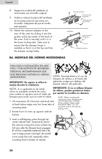
Page 70 - B6. MONTAJE DEL HORNO MIcROONDAs; IMPORTANTE: No agarre ni utilice la
8. asegure la unidad del ventilador al microondas con el tornillo original. 9. Vuelva a colocar la placa del ventilador en la misma posición que antes con el tornillo. asegúrese de que el tornillo esté ajustado. 10. attach the exhaust adaptor to the rear of the oven by sliding it into the guides at ...
Page 72 - C. COn RECIRCUlaCIón; c1. FIJE LA PLAcA DE MONTAJE A LA PARED
C1. fije la placa de montaje a la pared C2. Prepare el gabinete superior C3. Controle la placa del ventilador C4. acomode el horno microondas C5. Instale o cambie el filtro de carbón C. COn RECIRCUlaCIón (SIn VEnTIlaCIón, SIn COnDUCTO) fije la placa a la pared con los pernos acodados. Debe utilizars...
Page 73 - c4. MONTAJE DEL HORNO MIcROONDAs
Debe realizar los agujeros para los tornillos de soporte superior, un agujero lo suficientemente grande para que pase el cable de energía. lea las instrucciones de la PlanTIlla • PaRa El GabInETE SUPERIOR. Péguela debajo del gabinete superior. • Realice los agujeros siguiendo las • instrucciones de ...
Page 75 - c5. INsTALAcIÓN O cAMBIO DEL FILTRO DE cARBÓN
NOTA: El filtro de carbón fue instalado en fábrica. Siga estos pasos para reemplazar el filtro o para instalar un filtro después de convertir un modelo con ventilación a funcionamiento con recirculación. c5. INsTALAcIÓN O cAMBIO DEL FILTRO DE cARBÓN Retire los tornillos de la parte superior de la 1....
Page 76 - Haier america; Do Not Return This Product To The store; IMPORTANTE; No Devuelva Este Producto al Establecimiento compra.; IMPORTANT; Ne pas Réexpédier ce Produit au Magasin
Haier america new York, nY 10018 Printed in China Made in China fabriqué en Chine Hecho en China IMPORTANT Do Not Return This Product To The store If you have a problem with this product, please contact the “Haier customer satisfaction center” at 1-877-337-3639. DATED PROOF OF PURcHAsE, MODEL # AND ...