Graco RTX 1500SP - Manual

Graco RTX 1500SP – Manual, read for free online in PDF format. We hope this helps you resolve any issues you may have. If you have further questions, please contact us through the contact form.


Table of Contents:
- Page 2 – Models
- Page 3 – Warnings; WARNING
- Page 5 – Component Identification
- Page 6 – ITEM
- Page 7 – Preparation; Pressure Relief Procedure
- Page 8 – Auxiliary Air Compressor; Generators; Hose Lengths
- Page 9 – Hopper; Removing Hopper; Front Cover; Removing Cover
- Page 10 – Back Cover
- Page 11 – RotoFlexTM HD Pump; Disassembly
- Page 12 – Reassembly
- Page 13 – Hose Break-In Procedure
- Page 14 – Compressor and Motor Repair
- Page 17 – Compressor Rebuild Kit
- Page 19 – Removing and Replacing Belt; Removing Belt; Replacing Belt
- Page 21 – Roller Replacement
- Page 22 – Rotor Assembly Replacement
- Page 23 – Air Cylinder and Solenoid Valve
- Page 25 – Relief Valve and Flow Sensor Manifold
- Page 26 – Air Flow Sensor Replacement
- Page 27 – Troubleshooting
- Page 29 – Air Diagram
- Page 30 – Parts
- Page 31 – Parts List
- Page 38 – Technical Data
- Page 39 – Notes
- Page 40 – Graco Standard Warranty; Graco Information
310645S
Repair and Parts
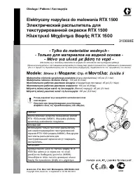
RTX 1500 Electric Texture Sprayer
- For Water-Based Materials Only -
(Consult your Material Supplier for Warnings and Application Requirements)
Models:
Page 2
Maximum Working Air Pressure:
45 psi (3.1 bar)
Maximum Working Fluid Pressure:
100 psi (6.9 bar)
Important Safety Instructions
Read all warnings and instructions in this
manual. Save these instructions.
NOTICE
Use RTX 1500 non-bleeder texture gun 248091.
All other guns will damage sprayer.
Related Manuals:
310645
Repair
ti4305a
RTX 1500
EN
RTX 1500 SP
ti25974a
"Loading the manual" means you need to wait until the file loads and becomes available for online reading. Some manuals are very large, and the time they take to appear depends on your internet speed.
Was this manual helpful?
About this manual
- Brand
- Graco
- Model
- RTX 1500SP
- Document type
- Manual
- Language(s)
- English
- Pages
- 40
- File size
- 2.4 MB
- Format
Summary
Models 2 310645S Models * Auxiliary Air Hookup Kit Manual Model Electric Requirements Country Operation 287328* Gun Languages 248201 120V, 60 Hz, 15 A N. America 31062 4 310694 31061 6 English 248536 110V, 60Hz, 15A UK 31062 4 310694 31061 6 English 248370 / 248315 230V. 50 Hz, 10 A Europe 31062 4 3...
Warnings 310645S 3 Warnings The following warnings are for the setup, use, grounding, maintenance, and repair of this equipment. The exclamation point symbol alerts you to a general warning and the hazard symbols refer to procedure-specific risks. When these symbols appear in the body of this manual...
Component Identification 310645S 5 Component Identification A C F H K L E B D P T U S R V W M ti4500a
Ask a question
Related manuals
Popular Graco Other
More Graco Other models
 Graco Reactor E-10 User Manual
 Graco Reactor E-XP2 User Manual
 Graco Rental Pro 360G Model 287513 Manual
 Graco RTX 900 Manual
- Graco RTX 1250 Manual
 Graco RTX 1500 Manual
 Graco SDM5 Manual
- Graco SDP15 Manual
- Graco Series A GMax II 5900HD Sprayer Model 249122 Manual
 Graco SG2 Manual
 Graco Silhouette Swing Manual
 Graco SnugRide Classic Connect 30 User Manual