Page 2 - Electrical requirements; SAFETY AND WARNINGS; Electric Shock Hazard; Fire Hazard; Failure to follow this advice may result in; Very Heavy; Failure to follow this advice may result in; SAVE THESE INSTRUCTIONS; Cut Hazard; Failure to use caution could result in injury.
2 WARNING! To avoid hazard, follow these instructions carefully before installing or using this appliance. z Save these instructions for the local inspectors use. z Please make this information available to the person installing the appliance — doing so could reduce your installation costs. z This o...
Page 4 - PRODUCT DIMENSIONS — SINGLE OVENS; PRODUCT DIMENSIONS
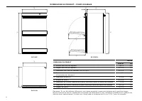
4 PRODUCT DIMENSIONS — SINGLE OVENS PLAN PROFILE FRONT G B A C F C D H PRODUCT DIMENSIONS OB30S INCHES MM A Overall height of product 27 1/8 690 B Overall width of product 29 15/16 760 C Overall depth of product (excl. handle and dials) 23 15/16 610 D Depth of oven front and control panel (excl. han...
Page 5 - CABINETRY DIMENSIONS — SINGLE OVENS; CABINETRY DIMENSIONS
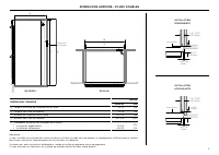
5 CABINETRY DIMENSIONS — SINGLE OVENS PLAN PROFILE e b a c d Electrical Supply CABINETRY DIMENSIONS OB30S INCHES MM A Minimum inside width of cavity 28 1/2 724 B Overall width of cabinetry 30 1/8 764 C Minimum inside height of cavity 26 13/16 681 D Overall height of cabinetry 27 3/8 693 E Minimum in...
Page 6 - PRODUCT DIMENSIONS — DOUBLE OVENS
6 PRODUCT DIMENSIONS — DOUBLE OVENS PRODUCT DIMENSIONS OB30D INCHES MM A Overall height of product 48 1/2 1232 B Overall width of product 29 15/16 760 C Overall depth of product (excl. handle and dials) 23 15/16 610 D Depth of oven front and control panel (excl. handle and dials) 1 1/2 40 E Depth of...
Page 7 - CABINETRY DIMENSIONS — DOUBLE OVENS
7 CABINETRY DIMENSIONS — DOUBLE OVENS CABINETRY DIMENSIONS OB30D INCHES MM A Minimum inside width of cavity 28 1/2 724 B Overall width of cabinetry 30 1/8 764 C Minimum inside height of cavity 48 3/16 1224 D Overall height of cabinetry 48 11/16 1236 E Minimum inside depth of cavity z Proud install z...
Page 8 - UPACKING THE OVEN; Single model shown for illustration purposes only
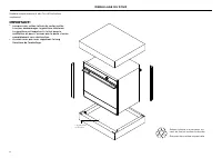
8 UPACKING THE OVEN Single model shown for illustration purposes only IMPORTANT! z When you remove the oven from the carton be careful not to damage the lower trim. The trim is important for both ventilation and to ensure the door opens fully without obstruction. z Ensure you remove the Long Trim fr...
Page 9 - Do not lift the oven door by its handle. Doing so may damage the door.
9 IMPORTANT! z Take care, the oven door is heavy. z Do not lift the oven door by its handle. Doing so may damage the door. z Ensure the oven and the door are cool before you begin to remove the door. z Before removing the door, ensure there is a large enough clear, protected surface in the kitchen t...
Page 10 - ELECTRICAL CONNECTION TO JUNCTION BOX; Connection methods
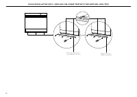
10 ELECTRICAL CONNECTION TO JUNCTION BOX If local codes permit connecting the cabinet-grounding conductor to the neutral (white) wire in the junction box: 1 Disconnect the power supply. 2 Remove the junction box cover. 3 Connect the oven cable to the junction box through the U.L. listed conduit conn...
Page 11 - SECURE THE OVEN TO THE CABINETRY
11 SECURE THE OVEN TO THE CABINETRY IMPORTANT! z Do not lift the oven by the door handle. z Do not over-tighten the screws. z Do not seal the oven into the cabinetry with silicone or glue. This makes future servicing difficult. Fisher & Paykel will not cover the costs of removing the oven, or of...
Page 13 - FINAL CHECKLIST; TO BE COMPLETED BY THE INSTALLER
13 FINAL CHECKLIST TO BE COMPLETED BY THE INSTALLER F F Ensure the oven is level and securely fitted to the cabinetry. F F Check the lower trim is undamaged. F F Open the oven door slowly until it is fully open and check there is adequate clearance between the bottom of the door and the lower trim. ...
Page 15 - Modèles; FOU R E N CAST R É; G U I D E D ’ I N S TA L L AT I O N
OB30S & OB30D Modèles FOU R E N CAST R É G U I D E D ’ I N S TA L L AT I O N U S C A
Page 16 - CONSIGNES DE SÉCURITÉ ET MISES EN GARDE; Risque de chocs électriques; Exigences électriques
2 ATTENTION! Pour éviter les dangers, suivez attentivement ces instructions avant d'installer ou d'utiliser cet appareil. z Conservez ces instructions afin de pouvoir les mettre à la disposition de l’inspecteur local. z Pour éviter les dangers, observez minutieusement ces instructions avant d’instal...
Page 17 - CONSERVER CES INSTRUCTIONS
3 APRÈS L’INSTALLATION PIÈCES FOURNIES AVANT L’INSTALLATION Visser Pour les modèles de fours simples (2) Pour modèles de fours doubles (4) Entretoises Pour les modèles de fours simples (2) Pour modèles de fours doubles (4) Le trim long (1) Pour être monté dans un montage encastré IMPORTANT! Certains...
Page 18 - DIMENSIONS DU PRODUIT - FOURS SIMPLES; DIMENSIONS DU PRODUIT
4 DIMENSIONS DU PRODUIT - FOURS SIMPLES EN PLAN DE PROFIL DE FACE G B A C F C D H DIMENSIONS DU PRODUIT OB30S POUCES MM A Hauteur hors tout de l’appareil 27 1/8 690 B Largeur hors tout de l’appareil 29 15/16 760 C Profondeur hors tout de l’appareil (sans la poignée) 23 15/16 610 D Profondeur du cadr...
Page 19 - DIMENSIONS ARMOIRE - FOURS SIMPLES; DIMENSIONS ARMOIRE
5 DIMENSIONS ARMOIRE - FOURS SIMPLES INSTALLATION PROÉMINENTE INSTALLATION AFFLEURANTE 5/8 – 13/16" (16-20mm) 1 – 5/8" (42mm) 1 – 5/8" (42mm) 5/8 – 13/16" (16-20mm) min 1/16" (2mm) min 1/16" (2mm) entretoises entretoises EN PLAN DE PROFIL e b a c d fourniture électrique DIMEN...
Page 20 - DIMENSIONS DU PRODUIT - FOURS DOUBLES
6 DIMENSIONS DU PRODUIT - FOURS DOUBLES EN PLAN DE PROFIL DE FACE G h B A C F E D i DIMENSIONS DU PRODUIT OB30D POUCES MM A Hauteur hors tout de l’appareil 48 1/2 1232 B Largeur hors tout de l’appareil 29 15/16 760 C Profondeur hors tout de l’appareil (sans la poignée) 23 15/16 610 D Profondeur du c...
Page 21 - DIMENSIONS ARMOIRE - FOURS DOUBLES
7 DIMENSIONS ARMOIRE - FOURS DOUBLES INSTALLATION PROÉMINENTE INSTALLATION AFFLEURANTE 5/8 – 13/16" (16-20mm) 1 – 5/8" (42mm) 1 – 5/8" (42mm) 5/8 – 13/16" (16-20mm) min 1/16" (2mm) min 1/16" (2mm) entretoises entretoises DIMENSIONS ARMOIRE OB30D POUCES MM A Largeur minimale d...
Page 22 - DÉBALLAGE DU FOUR
8 DÉBALLAGE DU FOUR Modèle unique montré à des fins d’illustration seulement IMPORTANT! z Lorsque vous retirez le four du carton veiller à ne pas endommager la garniture inférieure. La garniture est important à la fois pour la ventilation et pour s’assurer que la porte s’ouvre complètement sans obst...
Page 24 - BRANCHEMENT ÉLECTRIQUE DE LA BOÎTE DE JONCTION; Méthodes de connexion
10 BRANCHEMENT ÉLECTRIQUE DE LA BOÎTE DE JONCTION Si les codes locaux permettent de raccorder le conducteur de mise à la terre du module au fil blanc (neutre) de la boîte de jonction : 1 Débranchez l’alimentation. 2 Retirez le couvercle de la boîte de jonction. 3 Raccordez le câble du four à la boît...
Page 25 - SÉCURISER LE FOUR À L’ARMOIRE
11 SÉCURISER LE FOUR À L’ARMOIRE IMPORTANT! z Ne pas trop serrer les vis. z Renez soin de ne pas endommager la garniture inférieure du four. z Ne pas sceller le four dans l’armoire avec du silicone ou de la colle. Cela rend l’entretien avenir difficile. Fisher & Paykel ne couvrent pas les frais ...
Page 27 - LISTE DE VÉRIFICATION FINALE; À REMPLIR PAR L’INSTALLATEUR; FONCTIONNEMENT TEST
13 LISTE DE VÉRIFICATION FINALE À REMPLIR PAR L’INSTALLATEUR F F Ensure Assurez-vous que le four est à niveau et solidement fixés à l’armoire. F F Vérifiez la garniture inférieure est en bon état. F F Ouvrir le (inférieur) porte du four lentement jusqu’à ce qu’elle soit totalement ouverte et de véri...