Page 2 - GUIDE CONTENTS
2 GUIDE CONTENTS Preparations ........................................................................ 3 Thermostat details ............................................................... 5 Removal of your old thermostat........................................... 7 Mounting, wiring, and configuring ...
Page 3 - Precautions
3 1. PREPARATIONS Precautions • Do not exceed the specification ratings.• All wiring must conform to local and national electrical codes and ordinances.
Page 4 - Check package contents
4 1.1 Check package contents This package should contain the following items:• Thermostat• Mounting screws and wall anchors (x2)• 2 AA batteries• Terminal wire label stickers• Installation instructions 1.2 Gather tools Required:□ Small Phillips or Flat-head screwdriver □ Small pliers (needle-nose) □...
Page 5 - System button
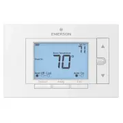
5 2. THERMOSTAT DETAILS The thermostat buttons and switches Fan buttonAway button (set a frequntly used temperature) System button Backlight button Raises temperature setting Access menu options Lowers temperature setting 1 2 3 4 5 6 7 8 9 10 11 12 13 14 15 16 17 18 19 20 1 2 3 4 5 6 7 8 9 10 11 12 ...
Page 6 - The display
6 Next (Menu button) is used to navigate within a menuBack (Fan button) is used to navigate within a menu Exit (Away button) returns to the home screenThermostat is protecting the equipment from short cycling (5-minute delay) Indicates that the system is running in Cool, Heat or Auxiliary mode. (Hea...
Page 7 - REMOVING OLD THERMOSTAT; changing the temperature on your old thermostat.; or
7 3. REMOVING OLD THERMOSTAT 3.1 Turn off power To ensure the power to your heating and cooling system has been turned off, try to turn on heating or cooling by changing the temperature on your old thermostat. or To prevent electrical shock and/or equipment damage, disconnect electrical power to the...
Page 8 - Remove the old thermostat cover; be released by using a screwdriver.
8 3.2 Remove the old thermostat cover Remove the old thermostat’s front cover form the wall base. Some covers pull off easily, while others may need to be released by using a screwdriver. 3.3 Label wires Tip: Taking a picture with a camera or smartphone can help you not only remember how wires are c...
Page 9 - Terminal labeling reference chart
9 3. Label that wire with the corresponding letter in the third column4. Disconnect the labeled wire carefully, and proceed to the next wire until all wires are labeledPlease note that not all terminals may be used and that there’s no standard color code for thermostat wires, so your wire colors may...
Page 10 - Terminal labeling reference chart, contʼd.
10 If your current terminal has the following letter Write down that letter here Label the wires with the following letters Terminal function W2** W2 2nd Stage Heat (Conventional) 2nd Stage Auxiliary Heat (Heat Pump) Y, Y1 Y 1st Stage Compressor Y2 Y2 2nd Stage compressor G G Fan Relay O, B*, O/B O/...
Page 13 - Remove old thermostat base
13 3.5 Remove old thermostat base With all of your wires disconnected and properly labeled, you may now safely remove the thermostat base from your wall. Tip: Worried about having your wires falling into your wall? Keep the wires secure by wrapping the them around a pencil.
Page 14 - thermostat base to the wall, if necessary.; Leveling Thermostat; Leveling is for appearance only and will not
14 4. MOUNTING AND WIRING YOUR NEW THERMOSTAT 4.1 Install new thermostat base Mount your new thermostat base using the supplied screws. Drill holes and insert wall anchors to secure the thermostat base to the wall, if necessary. Leveling Thermostat Leveling is for appearance only and will not affect...
Page 15 - Connect wires to corresponding terminal blocks
15 4.2 Connect wires to corresponding terminal blocks Match each labeled wire to it’s corresponding terminal on the mounted thermostat base. Insert each labeled wire into the hole of it’s matching terminal, and using the screwdriver, tighten the screw on the terminal block securely. RCRH O/B RH Take...
Page 16 - Identify system configuration; Thermostat Terminals
16 4.3 Identify system configuration Your wiring can help to determine the type of heating and cooling equipment installed in your home. Before attaching the front cover, use the following chart, and check the box next to the settings that match your new thermostat’s wiring. This information will be...
Page 18 - to find out your equipment type and old wirings.; AC2: setting of the item; installer menu
18 4.4 Install the batteries and attach front cover Install the included AA alkaline batteries and push the front cover on to the thermostat base until it’s secure. 4.5 Configure thermostat Hold the menu button down for 8 seconds to launch the installer menu. Your screen will change to the configura...
Page 19 - CR
19 User Menu # (Hold Menu 8 Seconds) Description Default Setting (flashing icons) Settings ( Press or ) 05 Outdoor Equipment: selects air conditioner (AC) or heat pump (HP) equipment as well as the number of stage AC2 AC0 AC1 AC2 HP1 HP2 Refer to Section 4.3 10 Indoor Equipment: selects whether the ...
Page 20 - valve as “B” at this step
20 * Setting reversing valve is necessary for heat pump users only. Please refer to the chart in section 3.3 for your old thermostat’s wiring. On your OLD thermostat• if you had a wire connected to “O” terminal, set reversing valve (menu # 20) valve as “O” at this step.• if you had a wire connected ...
Page 21 - CHECK THERMOSTAT OPERATION
21 4.6 Turn on power Turn on your power at the source.Congratulations! You’ve completed the thermostat installation process. 5. CHECK THERMOSTAT OPERATION 5.1 Fan operation If your system does not have a G terminal connection, skip to 5.2 Heating system.1. Press the fan button to select the On posit...
Page 23 - and the Cool On icon will disappear.; USING YOUR THERMOSTAT
23 5.4 Cooling system 1. Press the system button to select the Cool position. 2. Press to adjust thermostat setting 1° below room temperature. The blower should come on immediately on high speed, followed by cold air circulation. The thermostat will indicate Cool On. There can be up to a 5 minute de...
Page 25 - Thermostat operation; hold and the Menu button until the
25 6.2 Thermostat operation • Away – Store a frequently used temperature so that you can easily select that setting with the touch of a button. Set up by using or to change the set point. At the desired set point, hold the Away button for 3 seconds. Once the information is stored the set point will ...
Page 26 - SPECIFICATIONS
26 7 SPECIFICATIONS Electrical Rating: Battery Power ...................................................... mV to 30 VAC, NEC Class II, 50/60 Hz or DC Input-Harwire ....................................................... 20 to 30 VAC, NEC Class II, 50/60 HzTerminal Load ................................
Page 32 - other reproductive harm.
32 CONTACT US Customer support: 877.654.9394 or [email protected] MERCURY NOTICE This product does not contain mercury. However, this product may replace a product that contains mercury.Mercury and products containing mercury must not be discarded in household trash. Refer to thermostat-recycle.org ...