Emerson 1C20-102 - User Manual
Emerson 1C20-102 Thermostat – User Manual, read for free online in PDF format. We hope this helps you resolve any issues you may have. If you have further questions, please contact us through the contact form.


Table of Contents:
- Page 2 – MOUNTING AND WIRING; CAUTION; REMOVING OLD THERMOSTAT; CONTINUED FROM FIRST PAGE; TERMINAL CROSS REFERENCE CHART; WARNING
- Page 3 – Typical Zone Valve; Figure 6. Subbase switching and thermostat/system
- Page 4 – TROUBLESHOOTING
SUBBASE
(MODEL 1C26
ONLY)
BASE
COVER
ANTICIPAT OR
CAPTIVE SCREW S
MOUNTING SCREW S
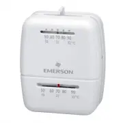
Figure 1.
Installation Instructions for
Heating only
1C20
and
Heating & Cooling
1C26
CONTENTS
Preparations ...........................................
Thermostat Features ..............................
Removing Old Thermostat .....................
Mounting and Wiring ..............................
Set Heat Anticipator ...............................
New Thermostat Operation ....................
Specifications .........................................
Troubleshooting ..................................... 8
PREPARATIONS
THERMOSTAT FEATURES
REMOVING OLD THERMOSTAT
Before removing wires from old thermostat’s switching subbase,
label each wire
with the terminal designation it was removed from.
Some models also include an
adaptor plate
to cover unpainted
surfaces. Thermostat wires pass through the adaptor plate center
opening.
1. Remove Old Thermostat:
A standard heat/cool thermostat
consists of three basic parts:
a. The cover, which may be either a snap-on or hinge type.
b. The base, which is removed by loosening all captive screws.
c. The switching subbase, which is removed by unscrewing
the mounting screws that hold it on the wall or adaptor plate.
Make a note here of the anticipator setting on
the old thermostat for future reference and use in step 5.
The heat anticipator pointer, if adjustable, will be set at one of a
series of numbers representing the current rating of the primary
control in your furnace. The number will be one of the following:
.2, .4, .8, etc. or 0.2, 0.4, 0.8, etc.
If no heat anticipator/indication is showing, do not be concerned;
move on to the next step.
PART NO. 37-6335B
Replaces 37-6335A
0835
Failure to follow and read all instructions carefully be-
fore installing or operating this control could cause
personal injury and/or property damage
Assemble tools required as shown below.
YOUR THERMOSTAT REPLACES
Adaptor Plate
(optional)
Description
1C20
1C26
Standard Heating & Cooling Systems - 4 or 5 wires
No
Yes
Standard Heat Only Systems
Yes
Yes
Millivolt Heat Only Systems - Floor or Wall Furnaces
Yes
Yes
Standard Central Air Conditioning
No
Yes
Gas or Oil Heat
Yes
Yes
Electric Furnace
Yes
Yes
Hydronic (Hot Water) Zone Heat - 2 Wires
Yes
Yes
Hydronic (Hot Water) Zone Heat - 3 Wires
No
No
Heat Pump (No Aux or Emergency Heat)
No
Yes
Heat Pump (with Aux or Emergency Heat)
No
No
Baseboard Electric Heating or Line Voltage (120 or 240 Volt)
No
No
1
2
3
WIRE CUTTER/STRIPPER
SPIRIT LEVEL OR PLUMB BOB AND LINE OPTIONAL—
THERMOSTAT MUST BE LEVEL TO WORK PROPERLY
FLAT BLADE SCREWDRIVER
HAND OR POWER
DRILL WITH 3/16 INCH
DRILL BIT, IF NEEDED
To prevent electrical shock and/or equipment damage,
disconnect electrical power to the system at the main
fuse or circuit breaker until installation is complete.
CAUTION
!
2
1
3
4
5
6
7
8
www.white-rodgers.com
"Loading the manual" means you need to wait until the file loads and becomes available for online reading. Some manuals are very large, and the time they take to appear depends on your internet speed.
Summary
1C20 (Heat Only Two Wire):A. Mount base and adaptor plate: Mount base and adaptor plate (optional) to wall using screws provided (see Fig. 1). B. Attach wires: Attach one wire to R and the other wire to W on base. C. Skip to Step #5. 1C26 (Heating and Cooling):A. Remove base from subbase: Loosen the...
SET HEAT ANTICIPATOR Set anticipator to match the setting of your old thermostat younoted in Step 3, or, the anticipator should be set to match thecurrent rating stamped on your main heating control. The heatanticipator is adjustable from 0.15 to 1.2 amps. Adjust the antici-pator by rotating the con...
Symptom Possible Cause Corrective Action No Heat/No Cool/No Fan 1. Blown fuse or tripped circuit breaker. Replace fuse or reset breaker. (common problems) 2. Furnace power switch to OFF. Turn switch to ON. 3. Furnace blower compartment door or Replace door panel in proper position to engage panel lo...